Page History
...
| Term | Description | |
|---|---|---|
| Adapter Board | Adapts the Reference Motor to the EDPS Board. | |
| Control Board | A Digilent Arty Z7 with the firmware containing the FOC algorithm necessary to control the | Driver Board |
| EDDP | Electronic Drive Development Platform. | |
| EDDP Kit | A kit consisting of the EDPS Board, the Reference Motor, the Adapter board and. | |
| EDPS | Electric Drive Power Stage. | |
| EDPS Board | A Trenz Electronic GmbH board TEC0053 used as EDPS. | |
| Reference Motor | The motor included in the EDDP Kit. This motor is of brushless type and is already mated with an encoder. | |
| Web UI | A user interface in the form of a web page permitting operating the EDDP. |
Requirements for the Functional Test
It is possible to run the default control firmware and GUI to verify the that the hardware is functionalThe purpose of the Functional Test is to verify the functionality of the hardware by using the default firmware supplied.
Following items are required in addition to the EDDP Kit:
...
| Note |
|---|
In order to pass EMC radiatied radiated emission (EN 55011) class B requirements option "Spread Spectrum" must be activated (standard setting). |
...
| Note |
|---|
Software version that was used in EMC test: (Visible in the GUI main screen) 2017-7-31 (SVN Tag 5745). |
| Scroll Pagebreak |
|---|
Requirements for the Development
Requrements Requirements for the development with SDSoC:
- All items listed under the Requirements for Functional Test.
- Basic knowledge of Xilinx All Programmable FPGA and/or SoC devices, basic knowledge of Xilinx SDK and C/C++ programming in order to be able to adapt the firmware to your requirements.
- A PC capable of running Xilinx SDSoC 2017.1 development environment.
- Valid A valid Xilinx SDSoC license or voucher.
Requirements for the development with HLS:
- All items listed under Requirements for Functional Test.
- Basic knowledge of Xilinx All Programmable FPGA and/or SoC devices, basic knowledge of Xilinx SDK and C/C++ programming in order to be able to adapt the firmware to your requirements.
- A PC capable of running Xilinx Vivado 2017.1
...
When delivered as full EDDP Kit several components are pre-assembled.
Motor Adapter Board
The default ( Reference ) Motor with Encoder is connected to the Driver EDPS Board using special "the Adapter Board " ( TEC0060). In the EDDP Kit the Motor is pre-assembled:
...
The Adapter Board is mounted to Driver EDPS Board using 5 x M6 screws (Labels 0V, A, B, C, 12V on Adapter Board) and with M3 screws and spacer - marked 12V at the left. This Adapter board "forwards" (the yellow arrow) the Drive board EDPS Board pre-driver supply (12V) to the DC Link main terminal on the Drive EDPS board, so that separate DC Link power supply is not needed allowing easy evaluation of the complete system.
...
Note terminal marked+DC must be left open when using the Adapter board!
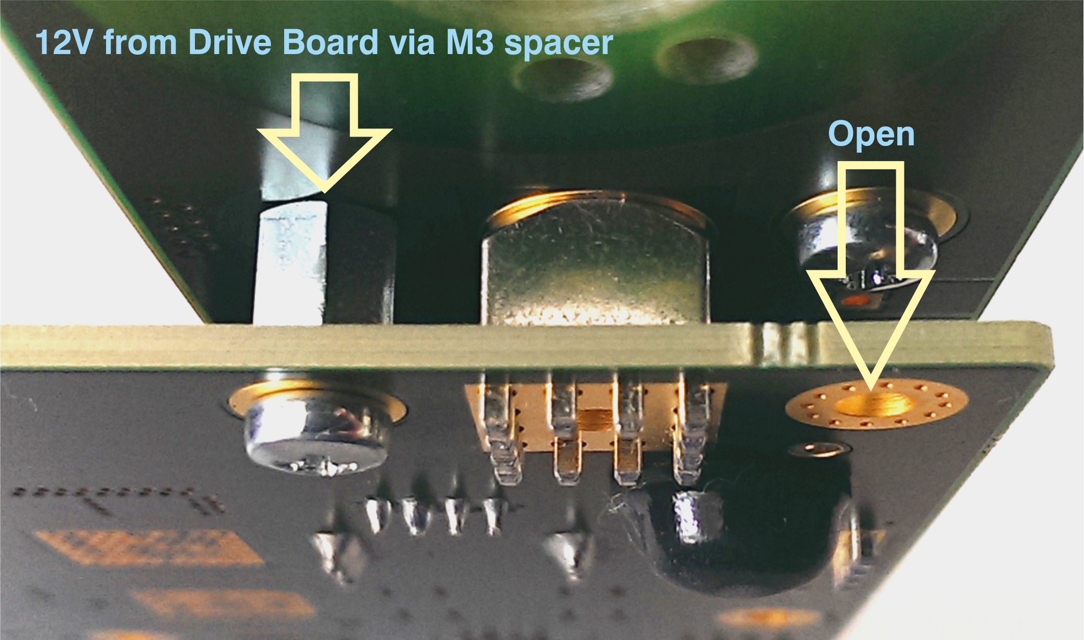
Figure 2: M3 M3 spacer and two M3 screws connect 12V from Drive the EDPS board to the Adapter board.
Motor Connection
When delivered as full In the EDDP Kit the reference Reference Motor stator wires for all three phases are already connected to the Adapter boardBoard. Instructions for manual assembly below:
...
Figure 3: Red dots and arrow mark the place where wire terminal can be released for insertion or removal.
Use Use a ball-point pen or similar tool to apply gentle force at the dot . Please do to release the wires. Do not try to remove the wires by simply pulling them out without releasing them first! Do not apply force in any other region of the white plastic except as marked, because it is easy to damage the plastic.
...
Notice that there are 5 pins in the Encoder header while the PMoD female connector has 6 terminals. Red Arrow marks the "empty" terminal at the PMoD Cable.
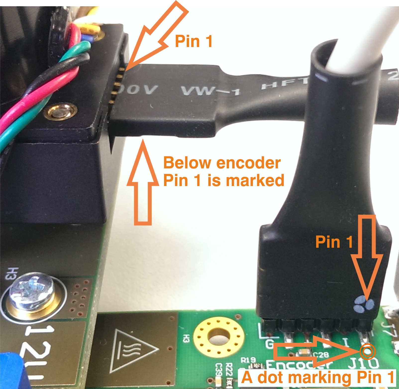
Figure 5: Pmod cable installation.
...
Overview
Content Tools