Page History
...
| Note |
|---|
Hardware components/boards delivered in EDDP Kit are not intended to be used in final products. All software and hardware parts of the EDDP are intended for developers evaluating Motor Control Applications with Xilinx FPGA and/or SoC devices. |
Use of Terms
The alphabetical list of specific terms and acronyms used in the EDDP User Manual and EDPS User Manual :are listed in the Table 1.
| Term | Description |
|---|---|
| Adapter Board | Adapts the Reference Motor to the EDPS Board. |
| Control Board | A Digilent Arty Z7 with the firmware containing the FOC algorithm necessary to control the |
| EDDP | Electronic Drive Development Platform. |
| EDDP Kit | A kit consisting of the EDPS Board, the Reference Motor, the Adapter board and. |
| EDPS | Electric Drive Power Stage. |
| EDPS Board | A Trenz Electronic GmbH board TEC0053 used as EDPS. |
| Reference Motor | The motor included in the EDDP Kit. This motor is of brushless type and is already mated with an encoder. |
| Web UI | A user interface in the form of a web page permitting operating the EDDP. |
Table 1: Terms and acronyms used.
Requirements for the Functional Test
...
- Control Board: ARTY-Z-7010
- EDPS Driver Board: TEC0053
- EDPS Motor Adapter Board: TEC0060
- EDPS Reference Motor with Encoder: BLRW-111D-24V-10000-1000-SI
- Plastic DEMO load for Motor
- One 6 Pin PMoD cable
- Two 12V Power Supplies
- Screws and other accessories used to mount the motor
- One spare M6 Screw
- Plastic cover for Driver Board use without TEC0060
- 30A Fuse for Driver Board use without TEC0060
- Micro SD Card
- Quickstart Guide
...
The software delivered on the SD card configures the FPGA on the ARTY-Z board with the Field-Oriented Control algorithm and starts the web server to serve the Web User Interface ( Web UI).
To access the EDDP Web UI, enter IP address of the Controller Board to the web browser address field. The following page appears:
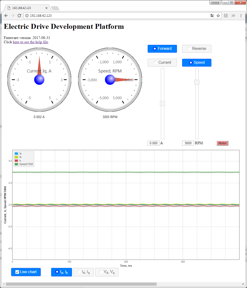
Figure 7: EDDP web The Web UI.
To start the motor, click the button "Motor". The motor will make 3 rotations in order to make sure that encoder finds the initial position before starting in correct mode and the button will turn red. To stop the motor, click the button "Motor" again; the button will turn green.
...
The radio buttons "Forward" and "Reverse" can be used to change the direction; the target slider will be changed accordingly.
Motor/Encoder
The default motor Reference Motor is supplied in the EDDP Kit; see the chapter Reference Motor in the EDPS User Manual for details. Use of custom motors is outside the scope of this manual.
...
A 3-phase permanent-magnet synchronous motor with attached encoder and mechanical load is mounted to a EDPS Driver Board TEC0053 by using an Adapter Board TEC0060. The Driver EDPS Board is connected to a Control Board ARTY-Z7 through PMOD connectors. A Host PC running a Web Browser connects to the Control Board through a Network.
On the Driver EDPS Board, the 3-phase power stage drives the motor according to the PWM signal. The current transducers on the Driver Board transform the phase currents on 2 (optionally 3) phases into voltages, which, along with the DC Link voltage, are converted by ADC-s into a delta-sigma bitstream. The encoder signals and the sigma-delta bitstream are passed through the galvanic isolation to the Control Board. The PWM signal and ADC clock from the Control Board are passed through the galvanic isolation as well.
...
- The data stream to the FOC algorithm consists of the concatenated stream of rotor angle and motor speeds and the stream of discrete ADC samples.
- The stream of PWM duty cycles from the FOC algorithm, which are converted to the PWM signals for the power stage.
- The stream of monitor data from the FOC algorithm, which is captured and written to the DMA buffer in the main memory. This monitor data stream can consist consists either of phase current data, stator current data or stator voltage data.
...
The Embedded Linux Code, running on the ARM Cortex-A9 CPU consists of the following:
- The Linux OS, that manages the hardware and provides execution environment for the programs to run in, which includes a TCP/IP network stack. The drivers included provide access to the control and status registers of the FOC algorithm and to the DMA buffer of the monitor data stream.
- The Network API is , a server program, which provides an API built on top of Websockets protocol to control and monitor the FOC algorithm and to capture the monitor data stream.
- The Web Server, which is used to host the Web UI.
...
Figure 8: Block diagram of the EDDP.
List of
...
additional documents
The additional documents, listed in the Table 2, can be downloaded from Trenz EDDP Web Hub:
| Title | Description |
|---|---|
| FOC SDSoC | Implementation of a Field-Oriented Control algorithm in C++ with Vivado SDSoC |
| SDSoC Hardware Platform ARTY-Z7 | A basis for building Vivado SDSoC applications running on an Arty-Z7 board connected to a TEC0053 board |
| AXI4-Stream AD7403 | An IP core for filtering the delta-sigma bitstream read from one or more ADC-s of type of AD7403 to an AXI4-Stream of samples |
| AXI4-Stream Encoder | An IP core for converting impulses from a relative index encoder with an index signal to an AXI4-Stream of position and speed data |
| AXI4-Stream PWM | An IP core for generating PWM signals according to the input AXI4-Stream |
| AXI4-Stream Concat | An IP core for concatenating AXI4-Streams |
| Web GUI | A Web UI to control and monitor an EDPS board over the Network API |
| Network API | A communication protocol, based on Websockets, to control an EDPS board |
| Embedded Linux Code | A server program interfacing to an EDPS board and implementing the Network API and the functions of a Web Server |
Table 12: List of the additional documents.
References
...
Overview
Content Tools