Page History
...
Pin 1 markings are indicated with the arrows, on the Drive Board a white dot marks 6-pin Pmod header pin 1. This pin should be aligned to Encoder Pin marked "G" and "1" visible when looking from the bottom up. Please note that Encoder header has 5 terminals while the driver board and Pmod cable have 6 terminals.
Troubleshooting network configuration on Windows
On Windows 7 and Windows 10, open the Control Panel and click on the Network and Sharing Center. The following window appears:
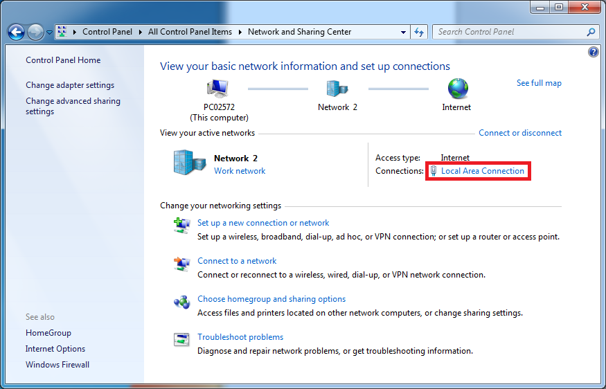
Figure 6: The Network and Sharing Centre, with the network connection used for communication with the Control Board highlighted.
Locate the network adapter that is to be used for communicating with the Control Board and click on it. The network connection status dialog appears (Figure 7).
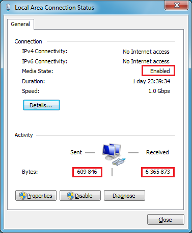
Figure 7: A network connection status dialog, with the media status and number of bytes sent and received highlighted.
For normal operation, the media state should read "Enabled".
During normal operation, the number of bytes sent ja received should increase when there is network traffic - e.g. when pinging the Control Board, when operating the Web UI, etc.
Viewing IP address
In the network connection status dialog (Figure 7), click "Details". A Network Connection Details dialog Local Area Connection Status dialog,
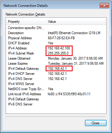
Figure 8: The Network Connection Details dialogue, with the important IP settings highlighted.
The
| Page break |
|---|
EDDP System Components
...
Overview
Content Tools