Page History
...
| Term | Description |
|---|---|
| Adapter Board | Adapts the Reference Motor to the EDPS Board. |
| Control Board | A Digilent Arty Z7 with the firmware containing the FOC algorithm necessary to control the |
| EDDP | Electronic Drive Development Platform. |
| EDDP Kit | A kit consisting of the EDPS Board, the Reference Motor, the Adapter board and. |
| EDPS | Electric Drive Power Stage. |
| EDPS Board | A Trenz Electronic GmbH board TEC0053 used as EDPS. |
| Host PC | A computer capable of running a web browser in order to run the Web UI. |
| Reference Motor | The motor included in the EDDP Kit. This motor is of brushless type and is already mated with an encoder. |
| Web UI | A user interface in the form of a web page permitting operating the EDDP. |
...
Pin 1 markings are indicated with the arrows, on the Drive Board a white dot marks 6-pin Pmod header pin 1. This pin should be aligned to Encoder Pin marked "G" and "1" visible when looking from the bottom up. Please note that Encoder header has 5 terminals while the driver board and Pmod cable have 6 terminals.
Troubleshooting network configuration on
...
the Host PC
It is assumed that the Host PC is running a Microsoft Windows 7 or newer operating system. For other operating systems, the basic network principles are the same, but the means of configuration are different; consult the corresponding user guides.
Open the Control Panel and click On Windows 7 and Windows 10, open the Control Panel and click on the Network and Sharing Center. The following window appears:
...
Figure 6: The Network and Sharing Centre, with the network connection used for communication with the Control Board highlighted.
Viewing network connection status
Locate the network adapter connection that is to be used for communicating communication with the Control Board and click on it. The network connection status dialog appears (Figure 7).
...
During normal operation, the number of bytes sent ja received should increase when there is network traffic - e.g. for example, when pinging the Control Board, when operating the Web UI, when pinging, etc.
Viewing IP address
In the network connection status dialog (Figure 7), click "Details". A Network Connection Details dialog Local Area Connection Status dialog,
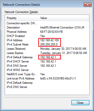
Figure 8: The Network Connection Details dialogue, with the important IP settings highlighted.
Checking network connectivity to the Control Board
On the Start Menu, select "All Programs" → "Accessories" → "Command Prompt. A command prompt window appears. Enter the command
ping IPwhere IP is the IP address of the Control Board. The result should be similar to the one shown on Figure 8.
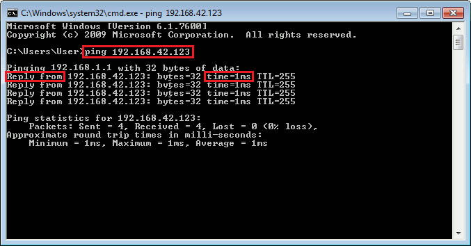
Figure 8: Successful check of network connectivity to the Control Board. The command entered by the user is highlighted, as are the important keywords that should be present in the output of the command "ping".
Verifying network adapter settings
In the network connection status dialog (Figure 7), click "Details". A Network Connection Details dialog Local Area Connection Status dialog,
Figure 8: A Network Connection Details dialogue, with the important IP settings highlighted.
The network settings should be such that the Control Board is reachable from the Host PC. In the case when they are in the same network segment, e.g. when the gateway is not involved, the following conditions should hold:
- The subnet mask should be the same for the Control Board and the Host PC.
- The IP addresses for the Control Board and Host PC must be different.
- The subnet mask divides the IP address into two parts according to the the bits set in the binary notation (255 in decimal = 11111111 in binary):
- The network address, which corresponds to the the bits set in the subnet mask. This should be the same for the Control Board and the Host PC.
- The host address, which corresponds to the bits not set in the subnet mask. This should be different for the Control Board and the Host PC. Additional constraint: it cannot be null and it cannot be the maximum value either.
On the example of settings shown on Figure 8 and the default configuration in the default firmware, the conditions are fulfilled as follows:
- The subnet mask, 255.255.255.0, is the same for both.
- The IP addresses, 192.168.42.100 for the Host PC and 192.168.42.123 for the Control Board, differ.
- The subnet mask checks out as follows:
- The network address, 192.168.42.0, is the same for the Host PC and the Control Board.
- The host addresses, 0.0.0.100 for the Host PC and 0.0.0.123 for the Control Board, are different. In addition, neither is 0 nor the maximum value, 255 in this case.
Changing the IP settings of a network connection
On the network connection status dialog (Figure 7), click "Properties". The following dialog (Figure 9) appears:
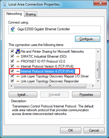
Figure 9: A network connection properties dialog. The item "Internet Protocol Version 4 (TCP/IPv4)" is selected and highlighted.
In the list of items used, select "Internet Protocol Version 4 (TCP/IPv4)" and click "Properties". The following dialog appears:
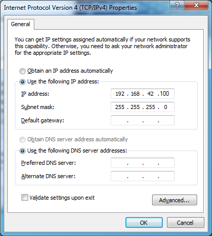
Figure 10: A TCP/IPv4 Properties dialog.
The settings on this dialogue have to match the actual network settings.
In most network setups, settings are as follows:
- Checked: Obtain an IP address automatically.
- Checked: Obtain DNS server address automatically.
In the case when using an network adapter dedicated solely for nothing else but communication with the Control Board, a static IP configuration (as shown on Figure 10) is to be used as follows:
- Checked: Use the following IP address:
- IP address: 192.168.42.100
- Subnet mask: 255.255.255.0
- Default gateway: not configured.
Other cases are not considered here; consultation with network administration or appropriate handbooks is recommended.The
| Page break |
|---|
EDDP System Components
The assembled EDDP Kit is shown on Figure 11.
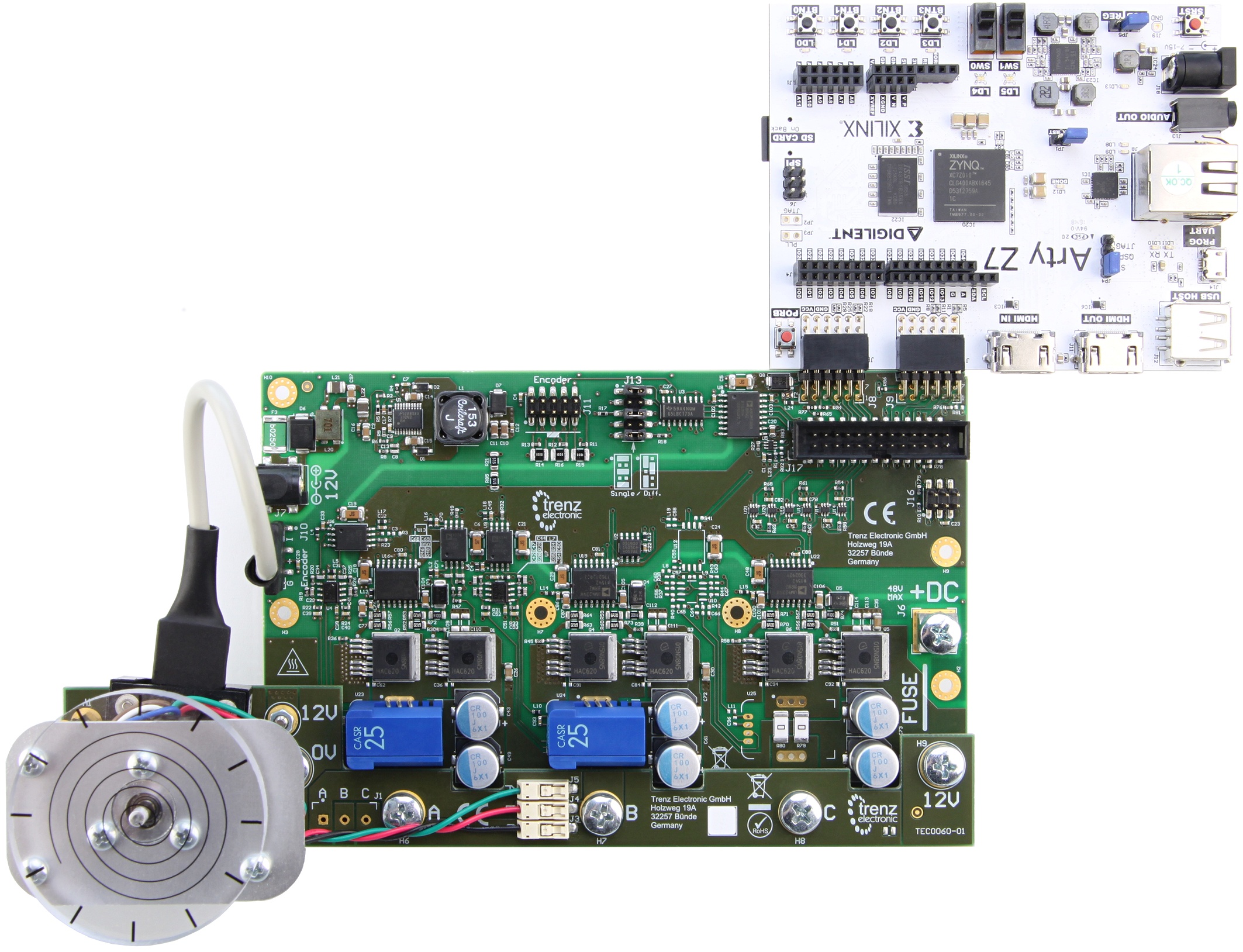
Figure 611: EDDP Kit assembly.
EDDP Kit Content
...
To access the EDDP Web UI, enter IP address of the Controller Board to the web browser address field. The following page appears:
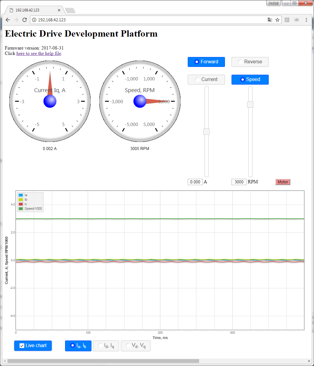
Figure 712: The Web UI.
To start the motor, click the button "Motor". The motor will make 3 rotations in order to make sure that encoder finds the initial position before starting in correct mode and the button will turn red. To stop the motor, click the button "Motor" again; the button will turn green.
...
The Web UI running in a web browser on the Host PC enables use of the EDDP Kit from anywhere in the network.
Block Diagram
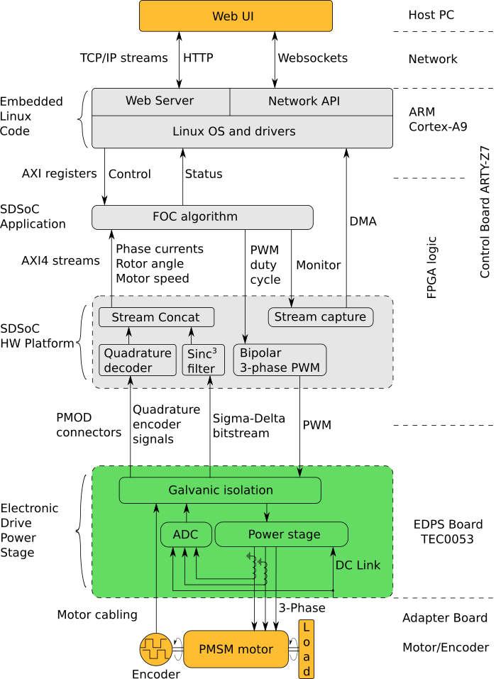
Figure 813: Block diagram of the EDDP.
...
Overview
Content Tools