Page History
...
Figure 8: Successful check of network connectivity to the Control Board. The command entered by the user is highlighted, as are the important keywords that should be present in the output of the command "ping".
Verifying network adapter settings
Note: After a recent change of network settings, it can happen that the ping is not successful because the changes haven't propagated to the other participiants on the network yet. It can be sometimes remedied by running the command "ping" on the other computer, in this case, on the Control Board, pinging the IP address of the Host PC.
Verifying network adapter settings
In the network connection status dialog (Figure 7), click "Details". A Network In the network connection status dialog (Figure 7), click "Details". A Network Connection Details dialog Local Area Connection Status dialog,
...
- The subnet mask, 255.255.255.0, is the same for both.
- The IP addresses, 192.168.42.100 for the Host PC and 192.168.42.123 for the Control Board, differ.
- The subnet mask checks out as follows:
- The network address, 192.168.42.0, is the same for the Host PC and the Control Board.
- The host addresses, 0.0.0.100 for the Host PC and 0.0.0.123 for the Control Board, are different. In addition, neither is 0 nor the maximum value, 255 in this case.
Changing the IP settings of a network connection
Alternative method of viewing network settings: Open command prompt (see Figure 8) and execute the following command:
ipconfigIt will list all netowork connections and their IP addresses.
Changing the IP settings of a network connection
On the network connection On the network connection status dialog (Figure 7), click "Properties". The following dialog (Figure 9) appears:
...
Software
The software delivered on the SD card configures the FPGA on the SD card configures the FPGA on the ARTY-Z board with the Field-Oriented Control algorithm and starts the web server to serve the Web UIthe ARTY-Z board with the Field-Oriented Control algorithm and starts the web server to serve the Web UI.
To observe the IP address of the Control Board, open the USB serial console at the baud rate of 115200 shortly after powering up the Control Board. There should be boot messages on the console and they should contain the IP address shown on the following Figure:
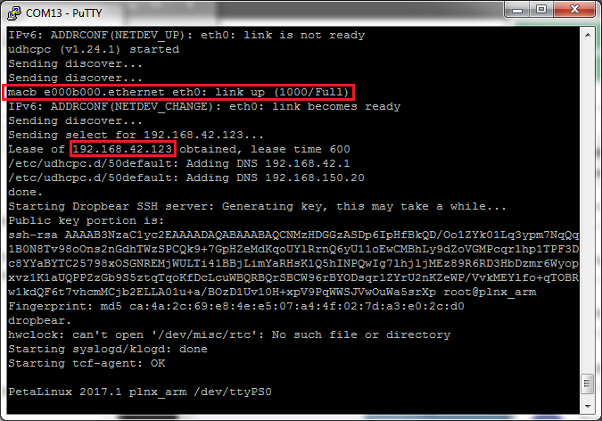
Figure 12: USB serial console log, with the network status message and IP address obtained via DHCP highlighted.
In the case the boot message was not seen for any reason, the network configuration can be seen by logging in as "root" with the password "root" and executing the command "ifconfig" as shown on the following figure:
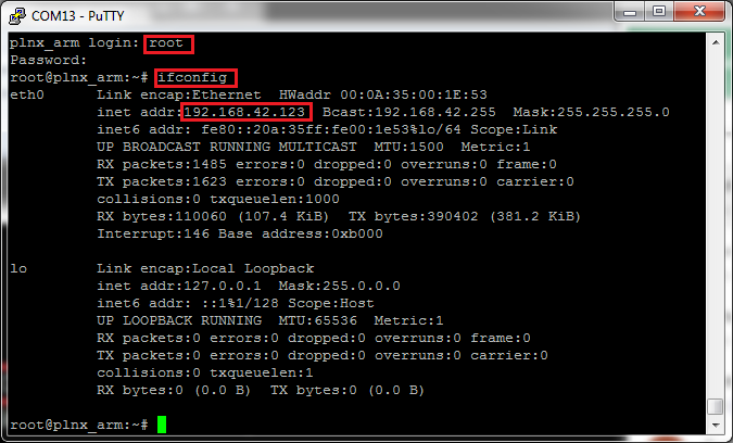
Figure 13: USB serial console, with login dialog, command "ifconfig" and the IP address highlighted.
To access the EDDP Web UI, enter IP address of the Controller Control Board to the web browser address field. The following page appears:
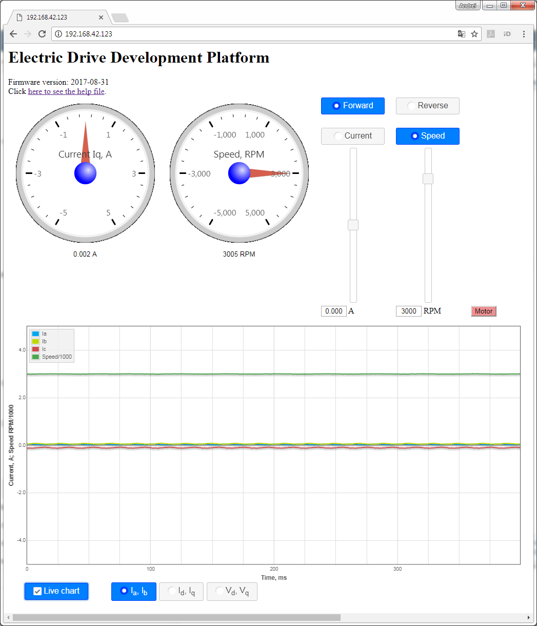
Figure 1214: The Web UI.
To start the motor, click the button "Motor". The motor will make 3 rotations in order to make sure that encoder finds the initial position before starting in correct mode and the button will turn red. To stop the motor, click the button "Motor" again; the button will turn green.
...
The Web UI running in a web browser on the Host PC enables use of the EDDP Kit from anywhere in the network.
Block Diagram
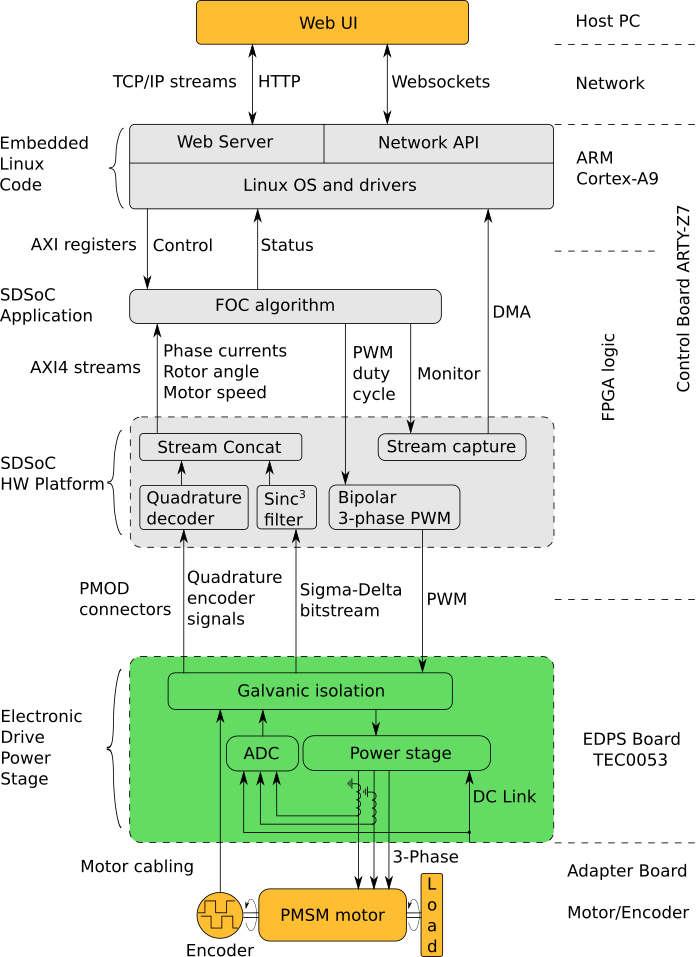
Figure 1315: Block diagram of the EDDP.
...
Overview
Content Tools