Page History
...
The Reference Motor with Encoder is connected to the EDPS Board using the Adapter Board TEC0060(see Figure 1). In the EDDP Kit the Motor is pre-assembled:.
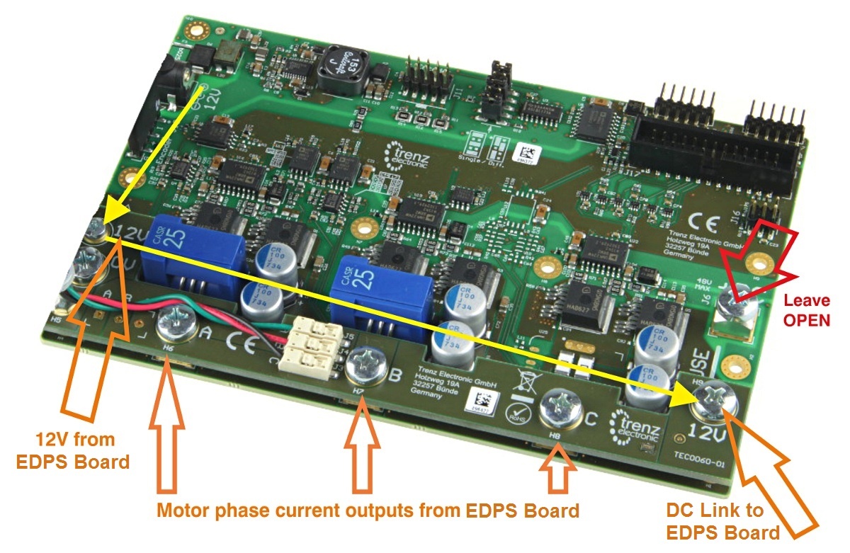
Figure 1: Top view of the EDPS Board with the Adapter Board mounted.
The Adapter Board is mounted to EDPS Board using 5 x M6 screws (Labels 0V, A, B, C, 12V on Adapter Board) and with M3 screws and spacer - marked 12V at the left. This Adapter board "forwards" (the yellow arrow) the EDPS Board pre-driver supply (12V) to the DC Link main terminal on the EDPS board, so that separate DC Link power supply is not needed allowing easy evaluation of the complete system.
...
Overview
Content Tools