Page History
...
| Scroll pdf ignore | |
|---|---|
|
Introduction
| Scroll Only (inline) |
|---|
Refer to https://wiki.trenz-electronic.de/display/PD/EDDP+User+Manual for online version of this manual and additional technical documentation of the product.
|
The Electronic Drive Development Platform (EDDP) provides all necessary software and hardware components for development and evaluation of motor control applications. While these components (both software and hardware) can also be used separately, this manual describes EDDP usage with default reference hardware platform (EDDP Kit) only.
...
| Term | Description | ||
|---|---|---|---|
| Adapter Board | Adapts the Reference Motor to the EDPS Board. | ||
| Control Board | An electronic board for controlling the EDPS Board; the EDDP Kit uses Digilent Arty Z7 for that purpose. | Control Board | A Digilent Arty Z7 with the firmware containing the FOC algorithm necessary to control the |
| EDDP | Electronic Drive Development Platform. | ||
| EDDP Kit | A kit consisting of the EDPS Board, the Reference Motor, the Adapter board and. | ||
| EDPS Board | Electric Drive Power Stage | .EDPS Board | A , the EDDP Kit contains a Trenz Electronic GmbH board TEC0053 to be used as an EDPS Board. |
| Host PC | A computer capable of running a web browser in order to run the Web UI. | ||
| Reference Motor | The motor included in the EDDP Kit. This motor is of brushless type and is already mated with an encoder. | ||
| Web UI | A user interface in the form of a web page permitting operating the EDDP. |
...
The Reference Motor with Encoder is connected to the EDPS Board using the Adapter Board (see Figure 1). In the EDDP Kit the Reference Motor is pre-assembled.
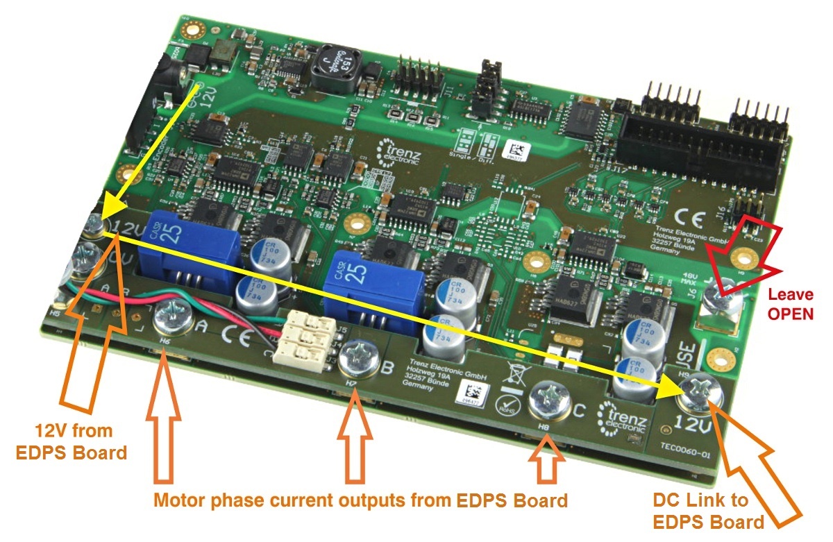
Figure 1: Top view of the EDPS Board with the Adapter Board mounted.
...
The Adapter Board is mounted to the EDPS Board using 5 x M6 screws (Labels 0V, A, B, C, 12V on Adapter Board) and with M3 screws and spacer - marked 12V at the left. This Adapter board "forwards" (the yellow arrow) the EDPS Board pre-driver supply (12V) to the DC Link main terminal on the EDPS board, so that separate DC Link power supply is not needed allowing easy evaluation of the complete system.
...
Note terminal marked+DC must be left open when using the Adapter board!
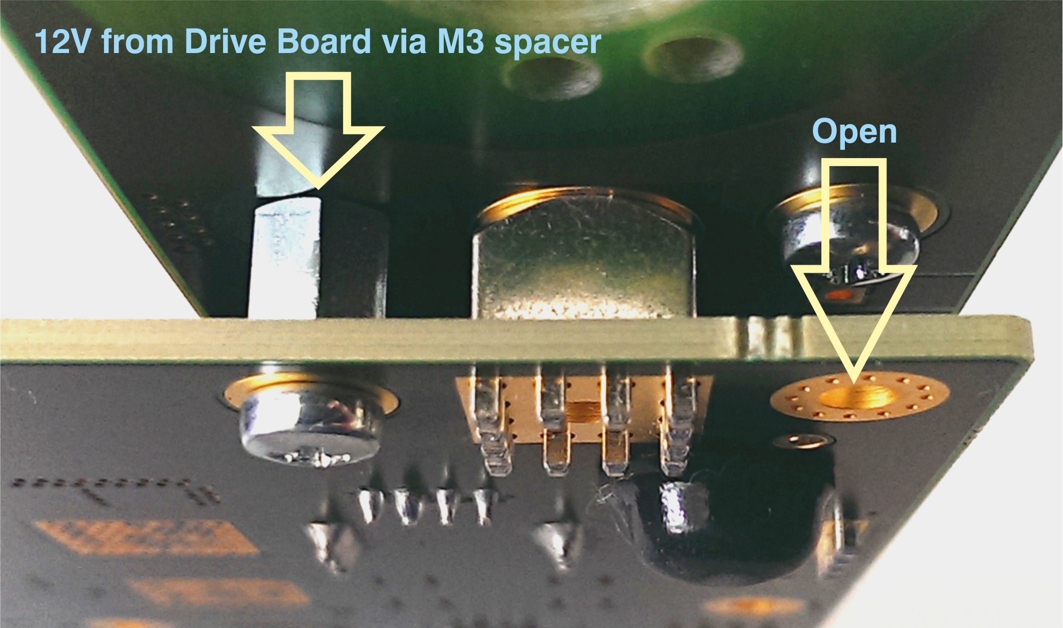
Figure 2: M3 spacer and two M3 screws connect 12V from the EDPS board to the Adapter board.
...
In the EDDP Kit the Reference Motor stator wires for all three phases are already connected to the Adapter Board. Instructions for manual assembly below:
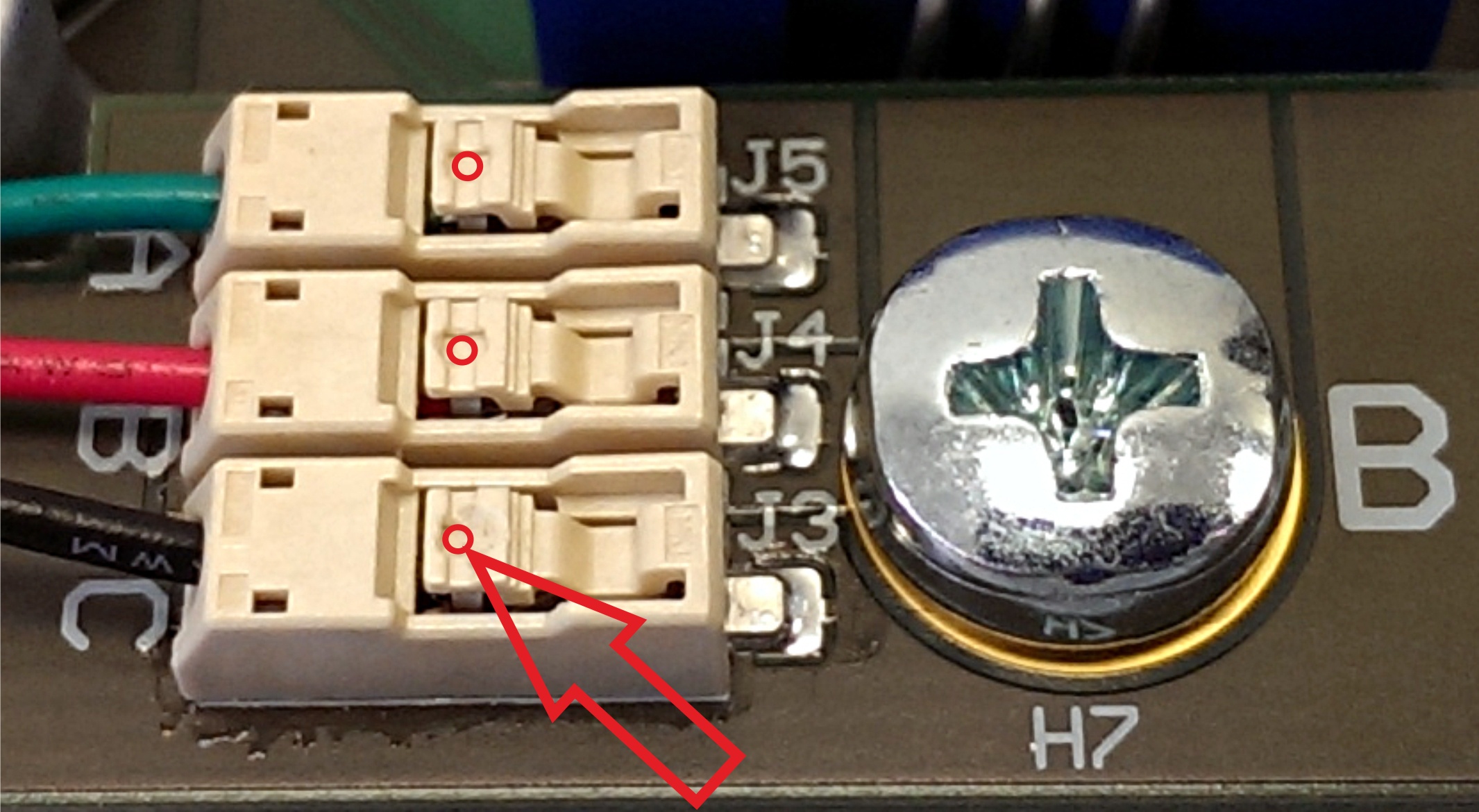
Figure 3: Red dots and arrow mark the place where wire terminal can be released for insertion or removal.
...
One 6-pin Pmod cable is included with the EDDP Kit. It is already assembled between encoder and Drive Board. Instructions for manual assembly are below:
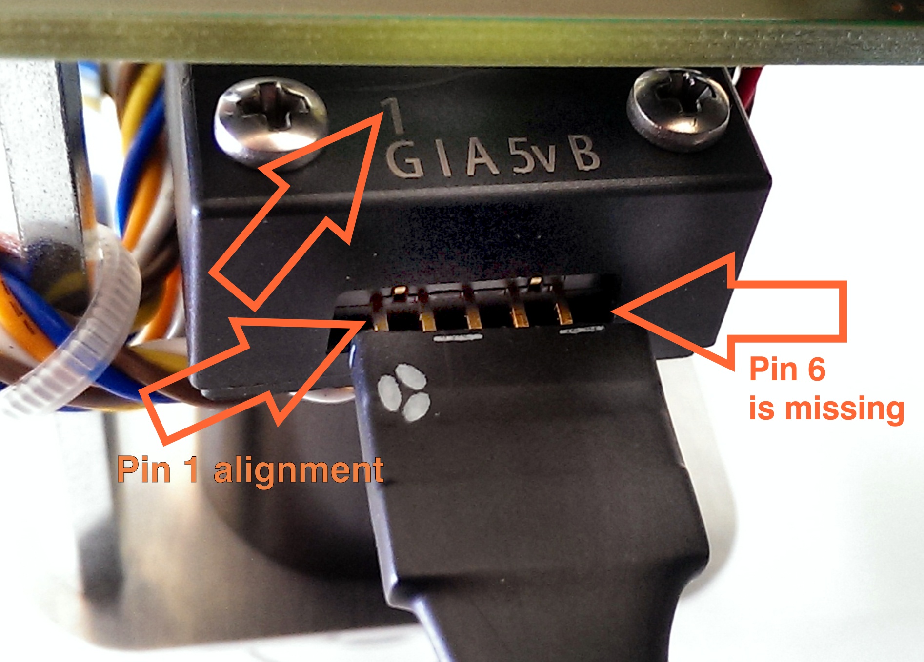
Figure 4: Pmod cable alignment to Encoder connector.
...
Notice that there are 5 pins in the Encoder header while the PMoD female connector has 6 terminals. Red Arrow marks the "empty" terminal at the PMoD Cable.
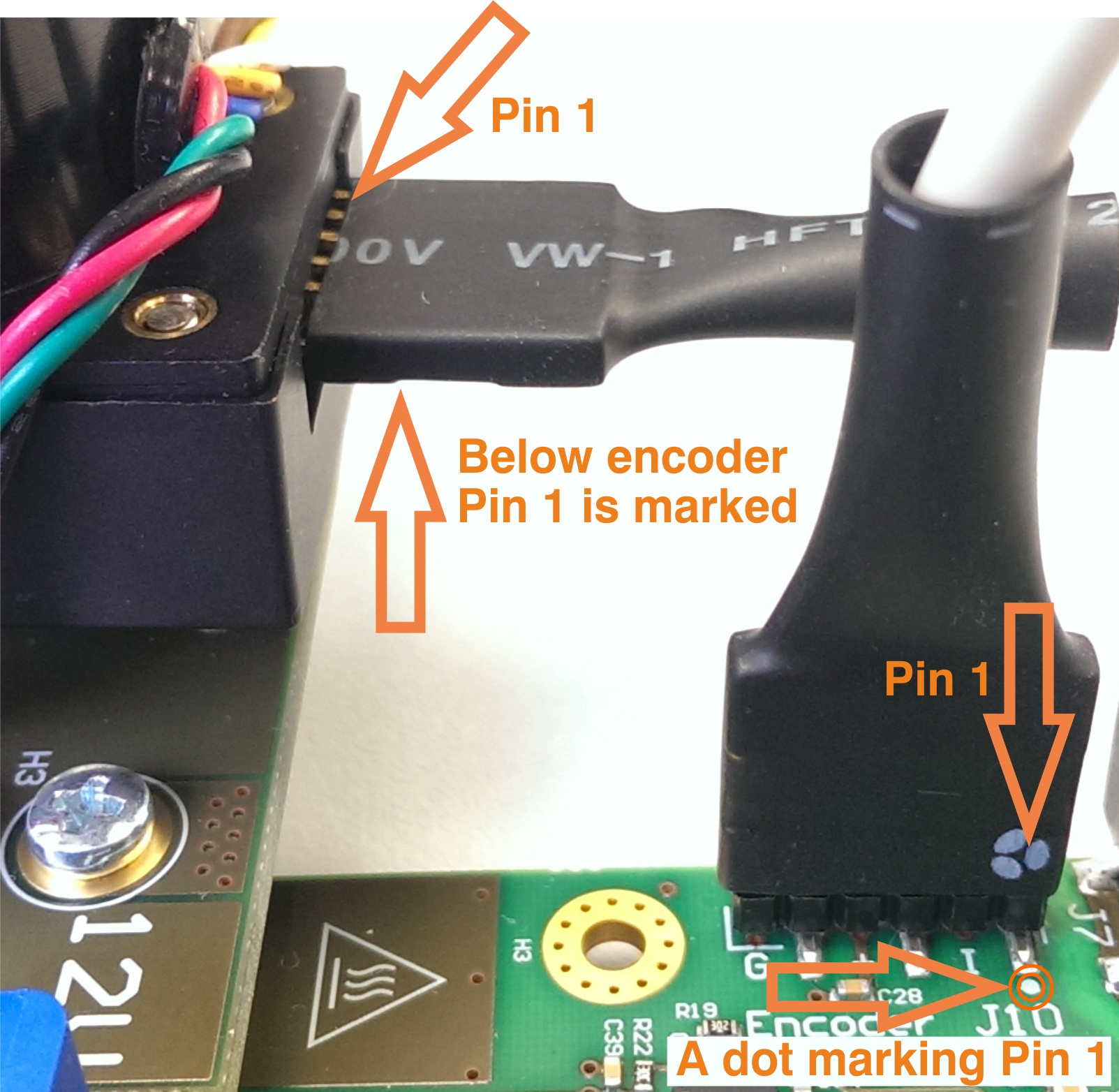
Figure 5: Pmod cable installation.
...
Locate the network connection that is to be used for communication with the Control Board and click on it. The network connection status dialog appears (Figure 7).
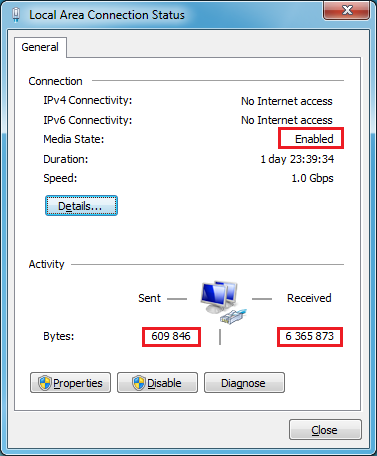
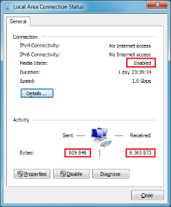
Figure 7: A network connection status dialog, with the media status and number of bytes sent and received highlighted.
...
where IP is the IP address of the Control Board. The result should be similar to the one on the following figure (Figure 8):
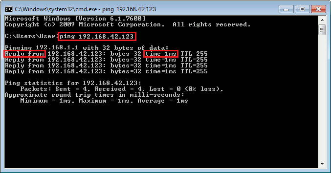
Figure 8: Successful check of network connectivity to the Control Board. The command entered by the user is highlighted, as are the important keywords that should be present in the output of the command "ping".
...
In the network connection status dialog (Figure 7), click "Details". A Network Connection Details dialog Local Area Connection Status dialog,
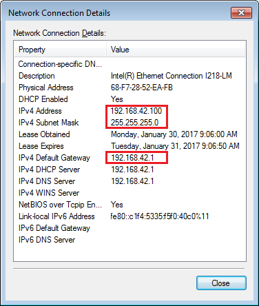
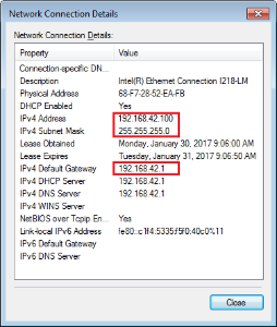
Figure 8: A Network Connection Details dialog, with the important IP settings highlighted.
...
On the network connection status dialog (Figure 7), click "Properties". The following dialog (Figure 9) appears:
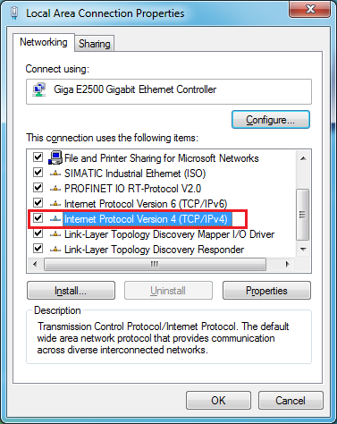

Figure 9: A network connection properties dialog. The item "Internet Protocol Version 4 (TCP/IPv4)" is selected and highlighted.
In the list of items used, select "Internet Protocol Version 4 (TCP/IPv4)" and click "Properties". The following dialog appears:
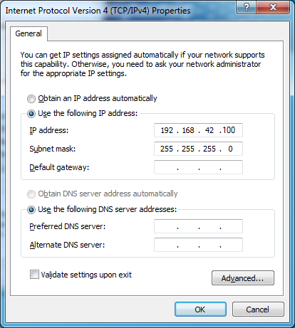
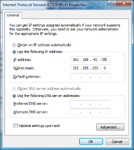
Figure 10: A TCP/IPv4 Properties dialog.
...
| Page break |
|---|
EDDP System Components
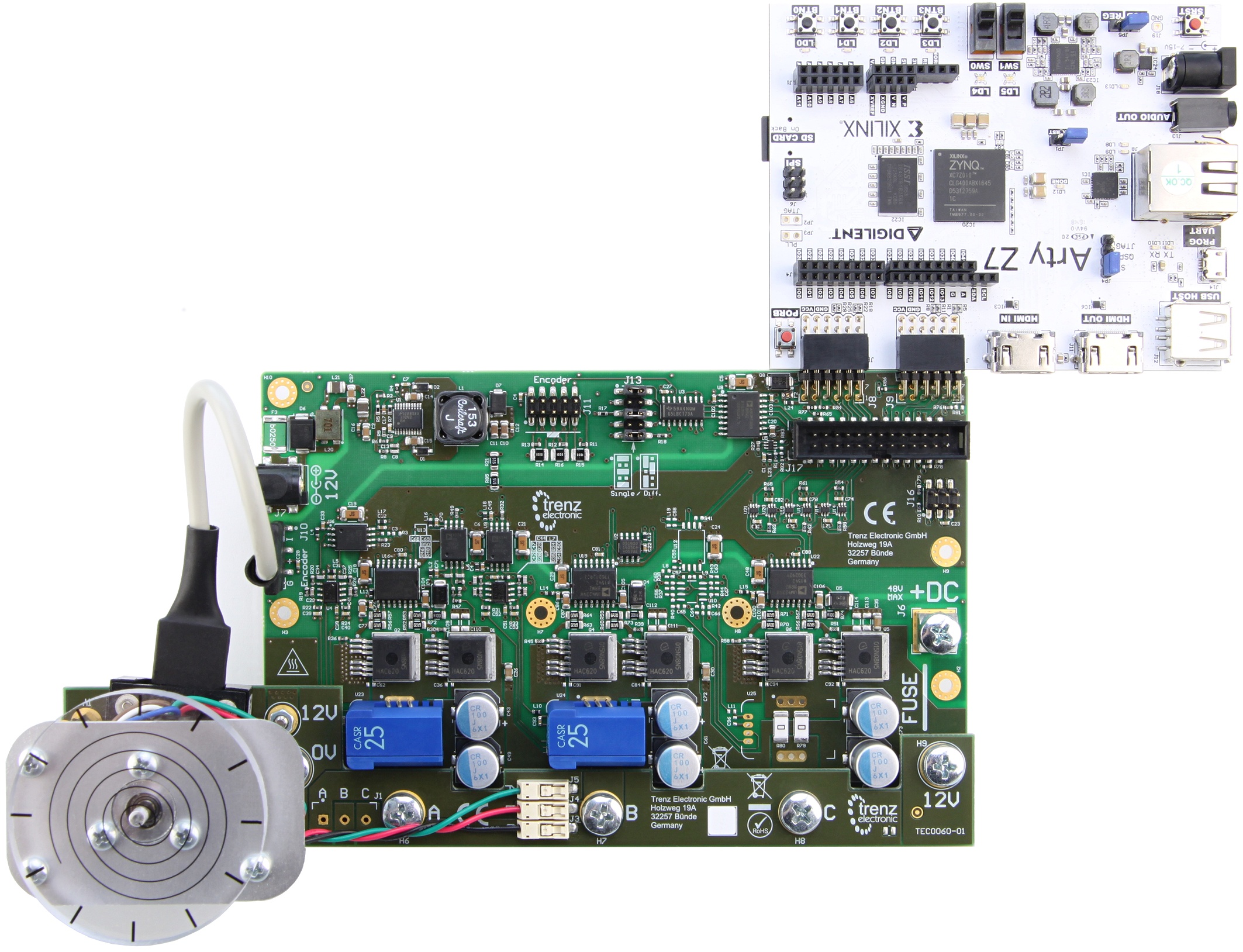
Figure 11: EDDP Kit assembly.
...
| Note |
|---|
The Motor is pre-mounted to the Driver board EDPS Board using the Adapter Board and accessories. |
...
The default Control Board is the Digilent ARTY-Z 7010, which is delivered as part of the EDDP Kit. This manual contains information relevent to the actual use of the ARTY-Z as a Control Board within the EDDP only; all technical data and user guides and manuals for the Controller Board are provided by the controller board manufacturer (Digilent Inc.). Use of the other Control boards with the EDPS Driver board EDPS Board is also outside the scope of this manual. Primary support for other control boards is currently provided by QDESYS.
...
To observe the IP address of the Control Board, open the USB serial console at the baud rate of 115200 shortly after powering up the Control Board. There should be boot messages on the console and they should contain the IP address shown on the following Figure:
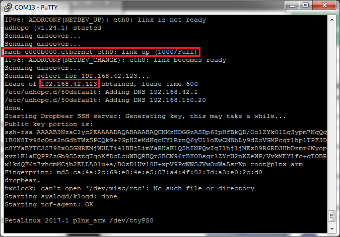
Figure 12: USB serial console log, with the network status message and IP address obtained via DHCP highlighted.
In the case the boot message was not seen for any reason, the network configuration can be seen by logging in as "root" with the password "root" and executing the command "ifconfig" as shown on the following figure:
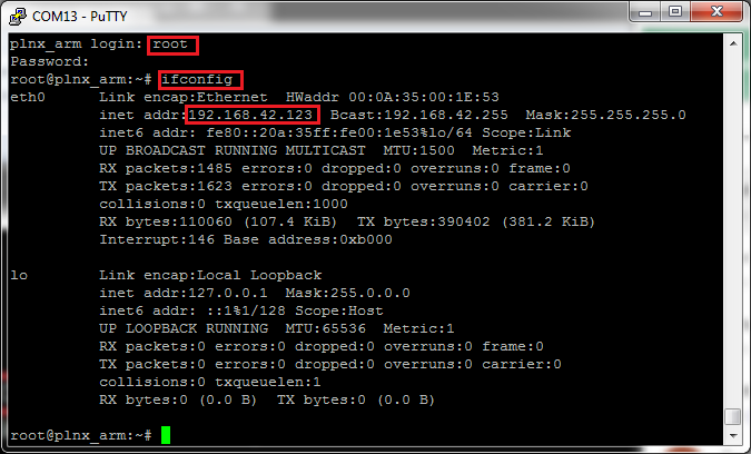
Figure 13: USB serial console, with login dialog, command "ifconfig" and the IP address highlighted.
...
To access the EDDP Web UI, enter IP address of the Control Board to the web browser address field. The following page appears:
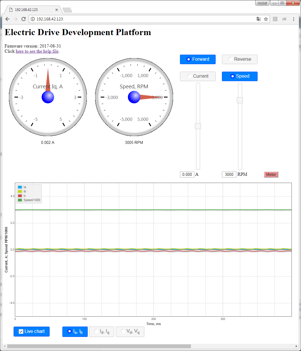
Figure 14: The Web UI.
...
The Web UI running in a web browser on the Host PC enables use of the EDDP Kit from anywhere in the network.
Block Diagram
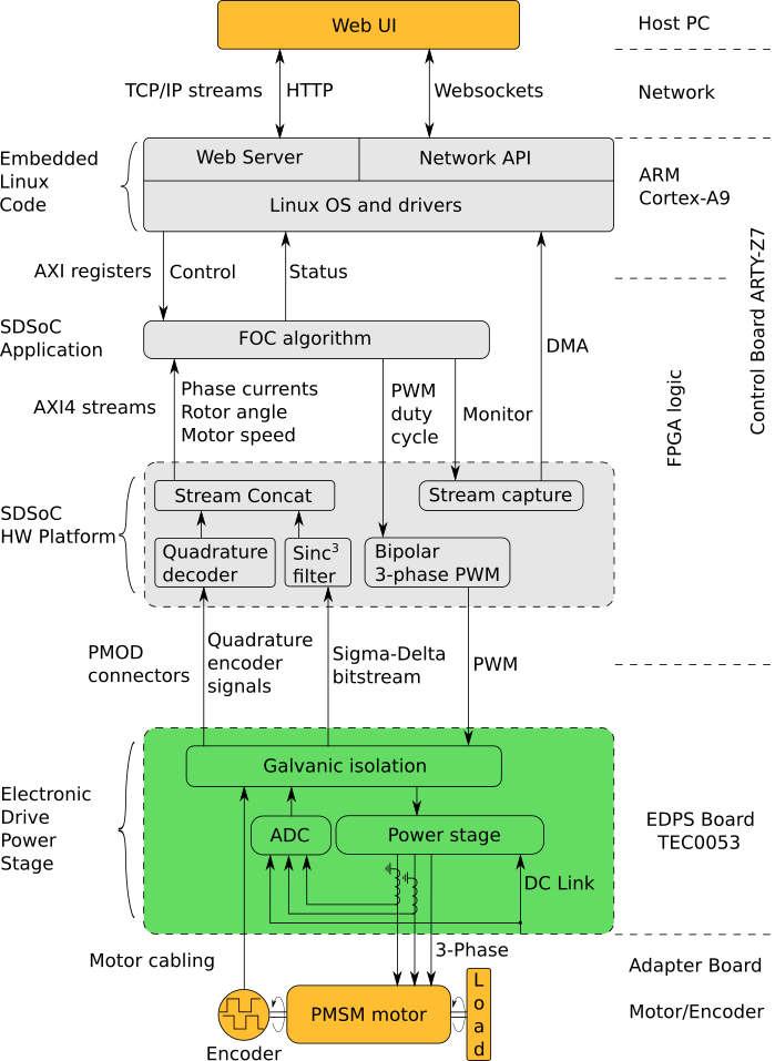
Figure 15: Block diagram of the EDDP.
...
| Title | Description |
|---|---|
| FOC SDSoC | Implementation of a Field-Oriented Control algorithm in C++ with Vivado SDSoC |
| SDSoC Hardware Platform ARTY-Z7 | A basis for building Vivado SDSoC applications running on an Arty-Z7 board connected to a TEC0053 board |
| AXI4-Stream AD7403 | An IP core for filtering the delta-sigma bitstream read from one or more ADC-s of type of AD7403 to an AXI4-Stream of samples |
| AXI4-Stream Encoder | An IP core for converting impulses from a relative index encoder with an index signal to an AXI4-Stream of position and speed data |
| AXI4-Stream PWM | An IP core for generating PWM signals according to the input AXI4-Stream |
| AXI4-Stream Concat | An IP core for concatenating AXI4-Streams |
| Web GUI | A Web UI to control and monitor an EDPS board Board over the Network API |
| Network API | A communication protocol, based on Websockets, to control an EDPS board |
| Embedded Linux Code | A server program interfacing to an EDPS board and implementing the Network API and the functions of a Web Server |
...
Overview
Content Tools