Page History
...
Figure 4: Pmod cable alignment to Encoder connectorthe Encoder connector.
Notice that there are 5 pins in the Encoder header while the PMoD female connector has 6 terminals. Red Arrow marks the "empty" terminal at the PMoD Cable.
...
Pin 1 markings are indicated with the arrows, on the Drive EDPS Board a white dot marks 6-pin Pmod header pin 1. This pin should be aligned to the Encoder Pin marked "G" and "1" visible when looking from the bottom up. Please note that Encoder header has 5 terminals while the driver board and Pmod cable have 6 terminals.
...
Locate the network connection that is to be used for communication with the Control Board and click on it. The network connection status dialog appears (Figure 7).
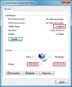
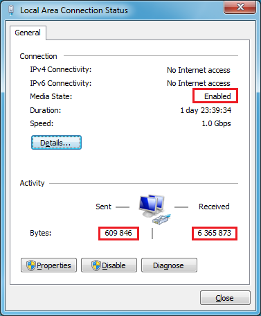
Figure 7: A network connection status dialog, with the media status and number of bytes sent and received highlighted.
...
In the network connection status dialog (Figure 7), click "Details". A Network Connection Details dialog appears:
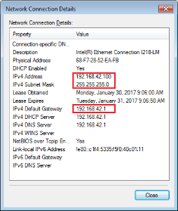
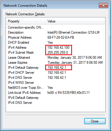
Figure 8: A Network Connection Details dialog, with the important IP settings highlighted.
...
On the network connection status dialog (Figure 7), click "Properties". The following dialog (Figure 9) appears:

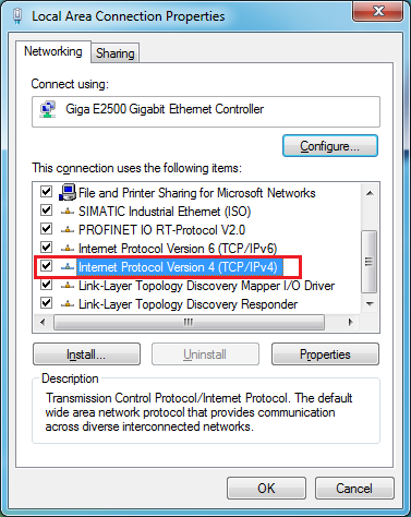
Figure 9: A network connection properties dialog. The item "Internet Protocol Version 4 (TCP/IPv4)" is selected and highlighted.
In the list of items used, select "Internet Protocol Version 4 (TCP/IPv4)" and click "Properties". The following dialog appears:
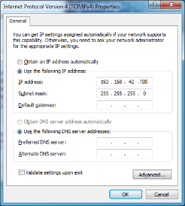
Figure 10: A TCP/IPv4 Properties dialog.
...
The Web UI running in a web browser on the Host PC enables use of the EDDP Kit from anywhere in the network.
Block Diagram
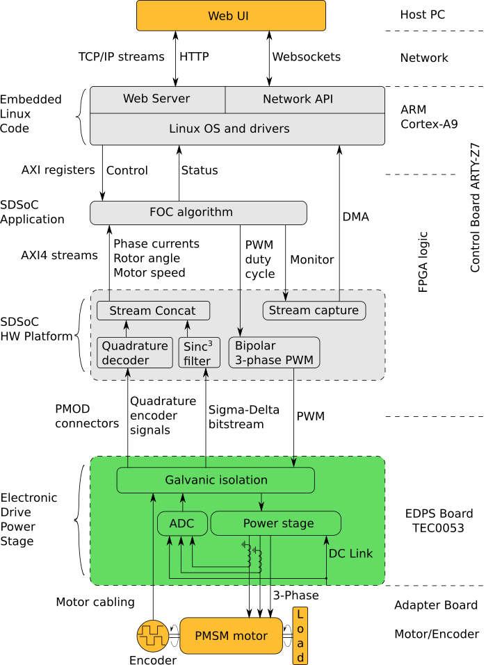
Figure 15: Block diagram of the EDDP.
...
Overview
Content Tools