Page History
...
| Date | Vivado | Project Built | Authors | Description |
|---|---|---|---|---|
2017-11-14 | 2017.2 | TE0803TE0807-test_board_noprebuilt-vivado_2017.2-build_05_2017111409071220171114115524.zip TE0803TE0807-test_board_noprebuilt-vivado_2017.2-build_05_2017111409072520171114115511.zip | John Hartfiel | initial release |
...
| Module Model | Board Part Short Name | PCB Revision Support | Notes |
|---|---|---|---|
| TE0803-ES1 | es1 | REV01 | |
| TE0803TE0807-01-02EG-1E | 2eg | REV01 | |
| TE0808-2ES2 | 2es2 | REV01 | TE0803-01-02CG-1E | 2cg | REV01 |
| ES2 | es2 | REV01 | |
| TE0803-01-03EG-1E | 3eg | REV01 | Different connector height |
| TE0803-01-03CG-1E | 3cg | REV01
Note: Design contains also Board Part Files for TE0803+TEBF0808 configuration, this boart part files are not used for this reference design.
...
Reference Design is available on:
- TE0803 TE0807 Test Board
Design Flow
| HTML |
|---|
<!-- Basic Design Steps Add/ Remove project specific --> |
...
- _create_win_setup.cmd/_create_linux_setup.sh and follow instructions on shell:
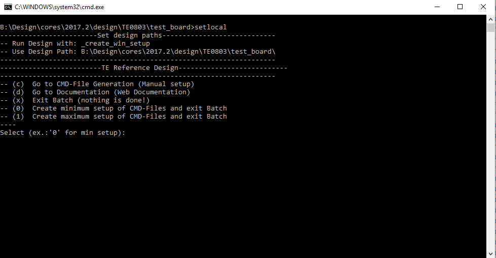
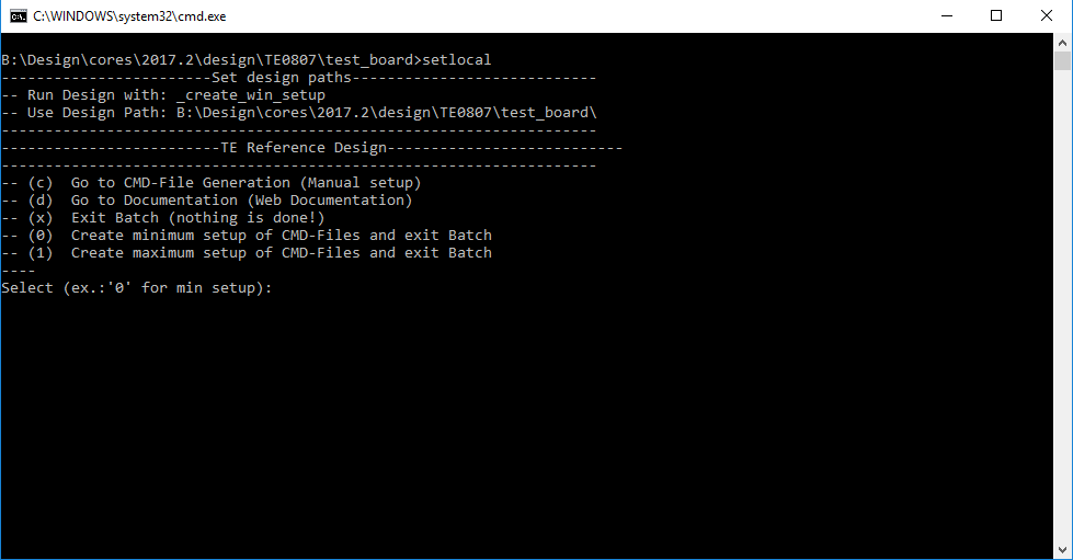
- Press 0 and enter for minimum setup
- (optional Win OS) Generate Virtual Drive or use short directory for the reference design (for example x:\<design name>)
- Create Project
- Select correct device and Xilinx install path on "design_basic_settings.cmd" and create Vivado project with "vivado_create_project_guimode.cmd"
Note: Select correct one, see TE Board Part Files
Use Board Part Files, which did not contains with *_tebf0808
- Select correct device and Xilinx install path on "design_basic_settings.cmd" and create Vivado project with "vivado_create_project_guimode.cmd"
- Create HDF and export to prebuilt folder
- Run on Vivado TCL: TE::hw_build_design -export_prebuilt
Note: Script generate design and export files into \prebuilt\hardware\<short dir>. Use GUI is the same, except file export to prebuilt folder
- Run on Vivado TCL: TE::hw_build_design -export_prebuilt
- Generate Programming Files with HSI/SDK
- Run on Vivado TCL: TE::sw_run_hsi
Note: Scripts generate applications and bootable files, which are defined in "sw_lib\apps_list.csv" - (alternative) Start SDK with Vivado GUI or start with TE Scripts on Vivado TCL: TE::sw_run_sdk
Note: See SDK Projects
- Run on Vivado TCL: TE::sw_run_hsi
...
- Prepare HW like described on section 46039248 TE807 Test Board
- Connect UART USB (most cases same as JTAG)
- Select QSPI Card as Boot Mode
Note: See TRM of the Carrier, which is used. - Power On PCB
Note: 1. ZynqMP Boot ROM loads PMU Firmware and FSBL from QSPI into OCM, 2. FSBL loads Application into DDR
...
Overview
Content Tools