Page History
...
| Scroll pdf ignore | |
|---|---|
Table of Contents
|
Overview
| Scroll Only (inline) |
|---|
https://wiki.trenz-electronic.de/display/PD/TEI0004+TRM for the current online version of this manual and other available documentation. |
...
The board is fully compatible with USB Blaster to program Intel (Altera) FPGA devices.
Key Features
- Fully compatible to Intel USB Blaster
- Additional UART interface available besides JTAG
- FTDI FT2232H USB2.0 Interface chip
- USB2.0 port High Speed (480 Mbps) and Full Speed (12 Mbps) compatible
- Entire USB protocol handled on the chip
- USB2.0 to JTAG, SPI and I²C conversion provided by the IC's Multi-Protocol Synchronous Serial Engine (MPSSE)
- USB2.0 to UART conversion
- Micro USB2.0 B socket connected to FTDI chip
- 93C56 EEPROM for configuration
- RED user LED
- 12 MHz clock from on-board Oscillator
- GREEN Power-on LED
Main Components
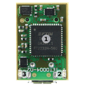
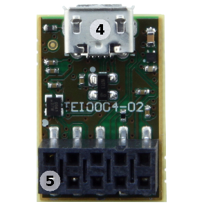
Figure 1: TE0790-02 main components.
- FTDI FT2232H IC
- RED LED (user)
- Green LED (Power-on)
- Micro USB2.0 B socket (receptacle)
- 2x5-pin female socket (pin 1 marked with white dot on PCB)
Signals, Interfaces and Pins
2x5 Female Socket
The 2x5 female socket have to be connected to the corresponding pin header on the target system. The signal assignment of the pin header on the adapter board is fully compatible to original USB blaster. Furthermore there is also an UART interface available and user configurable I/O pin (usable e.g. as Reset signal).
...
Table 1: 2x5-pin female socket pin-assignment.
USB Interface
The USB2.0 interface is provided by the FTDI FT2232H chip accessible by the Micro USB2.0 B (receptacle) socket. The entire USB protocol is handled on chip and compatible to USB2.0 High Speed (480 MBps) and Full Speed (12 MBps).
On-board Peripherals
FTDI FT2232H IC
The FTDI FT2232H chip provides a variety of industry standard serial or parallel interfaces. On the TEI0004 adapter board the interfaces USB2.0 to JTAG, UART and one user GPIO are available.
Refer to the FTDI data sheet to get information about the capacity of the FT2232H IC.
Configuration EEPROM
The external EEPROM can be used to customize the TEI0004 adapter board by setting numerous parameters of the FT2232H IC, enabling different functionalities and configuring serial or parallel interfaces.
The EEPROM is programmable in-circuit over USB using a utility program called FT_PROG available from FTDI’s web site (www.ftdichip.com).
On-board LEDs
The onOn-board LEDs indicates system status data transmission activitiesindicating power-on and user dependent:
| Color | Connected to | Description and Notes |
|---|---|---|
| Green | 3.3V | 3.3V power status LED |
| Red | FTDI IC | user configurable |
Table 2: On-board LEDs.
Power
Power supply of the adapter board
The TEI0004 USB2.0 adapter board is powered via USB supply voltage on the Micro USB2.0 socket.
Power Rails
Power Rail Name | 2x5-pin Female Socket | Micro USB2.0 B Socket | Direction | Notes |
|---|---|---|---|---|
| USB_VBUS | - | pin 1 | input | USB bus power, nominal voltage 5V ± 5% |
| VREF | pin 4 | - | input | Reference I/O-voltage of the target board |
Table 3: power Power rails.
Technical Specifications
Absolute Maximum Ratings
| Parameter | Min | Max | Units | Reference Document |
|---|---|---|---|---|
VREF | -0.5 | 4.6 | V | Nexperia 74AVCH4T245 data sheet |
| VBUS | 4.75 | 5.25 | V | USB2.0 Specification |
| Voltage on I/O pins | -0.5 | 4.6 | V | Nexperia 74AVCH4T245 data sheet |
| Storage temperature | -40 | 90 | °C | LED 19-213/R6C-AL1M2VY/3T data sheet |
Table 4: Module Board absolute maximum ratings.
Recommended Operating Conditions
| Parameter | Min | Max | Units | Reference Document |
|---|---|---|---|---|
VREF | 3.0 | 3.6 | V | USB Blaster specification |
| VBUS | 4.75 | 5.25 | V | USB2.0 Specification |
| Voltage on I/O pins | 0 | 3.6 | V | Nexperia 74AVCH4T245 data sheet |
| Operating temperature | -40 | 85 | °C | FTDI FT2232H data sheet |
Table 5: Module Board recommended operating conditions.
Operating Temperature Range
Industrial grade: -40°C to +85°C.
The TEI0004 USB2.0 adapter board is capable to be operated at industrial grade temperature range.
Revision History
Hardware Revision History
| Date | Revision | Notes | PCN | Documentation Link |
|---|---|---|---|---|
| - | 01 | prototypes | - | - |
| - | 02 | current available revision | - | TEI0004 |
Table 6: Module Board hardware revision history.
...
Hardware revision number can be found on the PCB board together with the module model number separated by the dash.
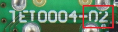
Figure 2: Module Board hardware revision number.
Document Change History
| HTML |
|---|
<!-- Generate new entry: 1.add new row below first 2.Copy "Page Information Macro(date)" Macro-Preview, Metadata Version number, Author Name and description to the empty row. Important Revision number must be the same as the Wiki document revision number 3.Update Metadata = "Page Information Macro (current-version)" Preview+1 and add Author and change description. --> |
...
Table 15: Document change history.
Disclaimer
| Include Page | ||||
|---|---|---|---|---|
|
...
Overview
Content Tools