Page History
...
| Module Model | Board Part Short Name | PCB Revision Support | Notes | |||
|---|---|---|---|---|---|---|
| te0720-03-2if | 2if | REV02, REV03 | ||||
Design supports following carriers:
...
Additional HW Requirements:
...
| te0720-03-2ifc3 | 2if | REV02, REV03 | lower connector |
| te0720-03-2ifc8 | 2if | REV02, REV03 | other eMMC size |
| te0720-03-1qf | 1qf | REV02, REV03 | |
| te0720-03-1cf | 1cf | REV02, REV03 | |
| te0720-03-2ef | 2ef | REV02, REV03 | |
| te0720-03-1cr | 1cr | REV02, REV03 | |
| te0720-03-l1if | l1if | REV02, REV03 | |
| te0720-03-14s-1c | 14s | REV02, REV03 |
Design supports following carriers:
| Carrier Model | Notes |
|---|---|
| TE0701 |
|
| TE0703 |
|
| TE0705 |
|
| TE0706 |
|
| TEBA0841 |
|
Additional HW Requirements:
| Additional Hardware | Notes |
|---|---|
| USB Cable for JTAG/UART | Check Carrier Board and Programmer for correct type |
| XMOD Programmer | Carrier Board dependent, only if carrier has no own FTDI |
Content
| HTML |
|---|
<!--
Remove unused content
--> |
For general structure and of the reference design, see Project Delivery
Design Sources
| Type | Location | Notes |
|---|---|---|
| Vivado | <design name>/block_design <design name>/constraints <design name>/ip_lib | Vivado Project |
Content
| HTML |
|---|
<!--
Remove unused content
--> |
For general structure and of the reference design, see Project Delivery
Design Sources
| Type | Location | Notes |
|---|---|---|
| Vivado | <design name>/block_design <design name>/constraints <design name>/ip_lib | Vivado Project will be generated by TE Scripts |
| SDK/HSI | <design name>/sw_lib | Additional Software Template for SDK/HSI and apps_list.csv with settings for HSI |
| PetaLinux | <design name>/os/petalinux | PetaLinux template with current configuration |
...
- _create_win_setup.cmd/_create_linux_setup.sh and follow instructions on shell:
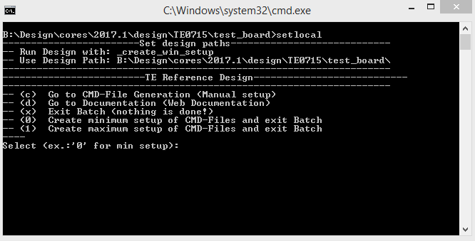
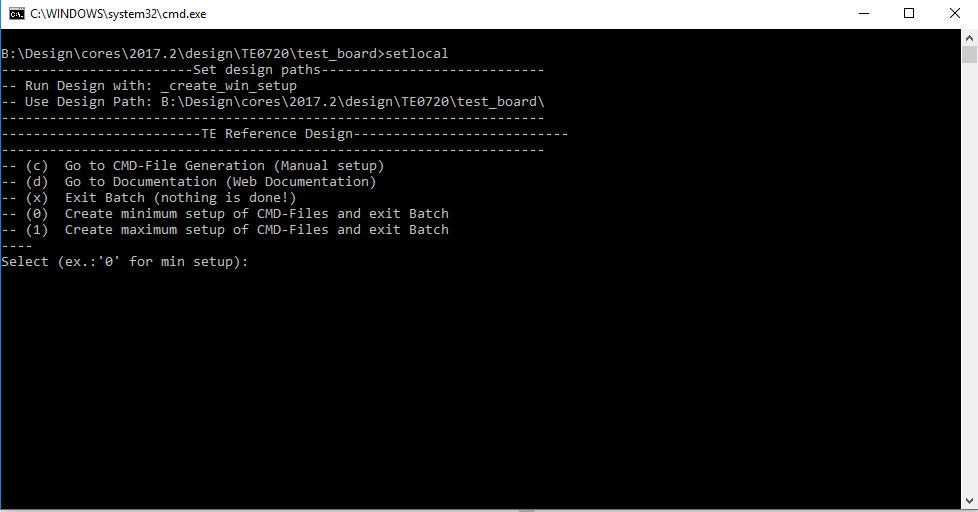
- Press 0 and enter for minimum setup
- (optional Win OS) Generate Virtual Drive or use short directory for the reference design (for example x:\<design name>)
- Create Project
- Select correct device and Xilinx install path on "design_basic_settings.cmd" and create Vivado project with "vivado_create_project_guimode.cmd"
Note: Select correct one, see TE Board Part Files
- Select correct device and Xilinx install path on "design_basic_settings.cmd" and create Vivado project with "vivado_create_project_guimode.cmd"
- Create HDF and export to prebuilt folder
- Run on Vivado TCL: TE::hw_build_design -export_prebuilt
Note: Script generate design and export files into \prebuilt\hardware\<short dir>. Use GUI is the same, except file export to prebuilt folder
- Run on Vivado TCL: TE::hw_build_design -export_prebuilt
- Create Linux (uboot.elf and image.ub) with exported HDF
- HDF is exported to "prebuilt\hardware\<short name>"
Note: HW Export from Vivado GUI create another path as default workspace. - Create Linux images on VM, see PetaLinux KICKstart
- Use TE Template from /os/petalinux
Note: run init_config.sh before you start petalinux config. This will set correct temporary path variable.
- Use TE Template from /os/petalinux
- HDF is exported to "prebuilt\hardware\<short name>"
- Add Linux files (uboot.elf and image.ub) to prebuilt folder
- "prebuilt\os\petalinux\default" or "prebuilt\os\petalinux\<short name>"
Notes: Scripts select "prebuilt\os\petalinux\<short name>", if exist, otherwise "prebuilt\os\petalinux\default"
- "prebuilt\os\petalinux\default" or "prebuilt\os\petalinux\<short name>"
- Generate Programming Files with HSI/SDK
- Run on Vivado TCL: TE::sw_run_hsi
Note: Scripts generate applications and bootable files, which are defined in "sw_lib\apps_list.csv" - (alternative) Start SDK with Vivado GUI or start with TE Scripts on Vivado TCL: TE::sw_run_sdk
Note: See SDK Projects
- Run on Vivado TCL: TE::sw_run_hsi
SDSoC (only tested on Win OS)
Note: See SDK Projects
- Generate Platform Project or use prebuilt from download
- ...
Launch
Programming
| HTML |
|---|
<!-- Description of Block Design, Constrains... BD Pictures from Export... --> |
...
- Prepare HW like described on section Programming
- Connect UART USB (most cases same as JTAG)
- Select SD Card as Boot Mode
Note: See TRM of the Carrier, which is used. - Power On PCB
Note: 1. Zynq Boot ROM loads FSBL from SD into OCM, 2. FSBL loads U-boot from SD into DDR, 3. U-boot load Linux from SD into DDR
Linux
- load Linux from SD into DDR
Linux
- Open Serial Console (e.g. putty)
- Speed: 115200
- COM Port: Win OS, see device manager, Linux OS see dmesg |grep tty (UART is *USB1)
- Linux Console:
Note: Wait until Linux boot finished For Linux Login use:- User Name: root
- Password: root
- You can use Linux shell now.
- I2C 0 Bus type: i2cdetect -y -r 0
- I2C 1 Bus type: i2cdetect -y -r 1
- RTC check: dmesg | grep rtc
- ETH0 works with udhcpc
Vivado HW Manager
PHY LED:
- Open Serial Console (e.g. putty)
- Speed: 115200
- COM Port: Win OS, see device manager, Linux OS see dmesg |grep tty (UART is *USB1)
- Linux Console:
Note: Wait until Linux boot finished For Linux Login use: - User Name: root Password: rootOpen Vivado HW-Manager and add VIO signal to dashboard (*.ltx located on prebuilt folder).
System Design - Vivado
| HTML |
|---|
<!-- Description of Block Design, Constrains... BD Pictures from Export... --> |
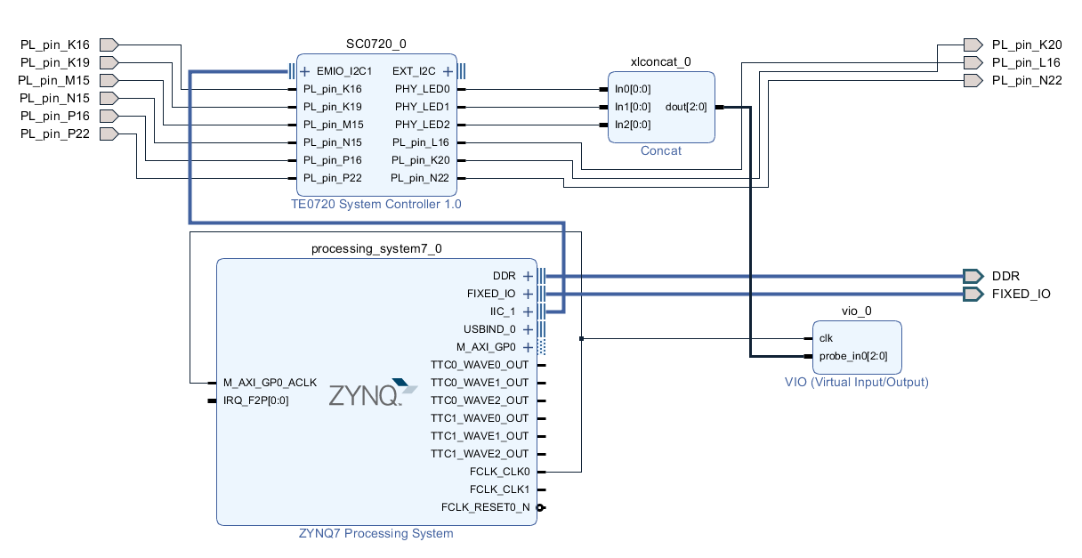
Block Design
PS Interfaces
Constrains
Basic module constrains
...
Overview
Content Tools