Page History
...
The voltages 1.0V (core voltage) and 3.3V are monitored by the voltage monitor circuit U6, which generates the POR_B reset signal at power-on. A manual reset is also possible by driving the connector pin P1-10 ('NRST') to GND. Leave this pin unconnected or connect to VDD (3.3V) when unused.
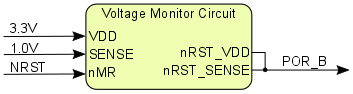
Figure 5: Voltage monitor circuit
Power Rails
Power Rail Name | J1 Pins | J2 Pins | J3 Pins | P1 Pin | P2 Pin | Direction | Notes |
|---|---|---|---|---|---|---|---|
| 3.3V | 5, 6 | 5, 6 | 5, 6 | 9 | 9 | Input / Output | 3.3V power supply voltage |
Table 13: Board power rails
Bank Voltages
Bank | Bank I/O Voltage VCCO | Voltage Range |
|---|---|---|
| 0 (config) | 3.3V | fixed |
| 500 (MIO) | 3.3V | fixed |
| 501 (MIO) | 3.3V | fixed |
| 34 (HR) | 3.3V | fixed |
| 35 (HR) | 3.3V | fixed |
Table 14: Board bank voltages
...
Overview
Content Tools