Page History
...
| HTML |
|---|
<!-- Wiki Link: Go to Base Folder of the Module or Carrier, for example : https://wiki.trenz-electronic.de/display/PD/TE0712 --> |
The Trenz Electronic TEF0008 is a FPGA to Mezzanine Card (FMC) based on VITA 57.1 FMC HPC Standard, with four SFP+ 10Gb fiber optical (850nm) ports. It is inteded for use on a FMC HPC carrier and can not be used stand-alone.
...
Figure 1: TEF0008-01 block diagram.
Main Components
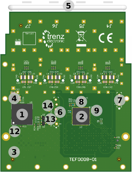
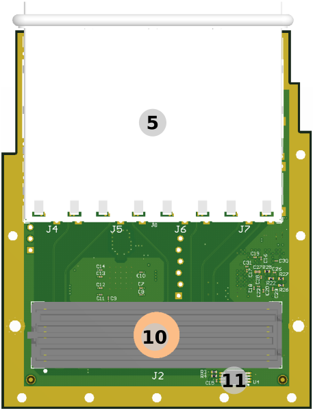
Figure 2: TEF0008-01 FMC overview.
...
Storage device name | Content | Notes | |||||
|---|---|---|---|---|---|---|---|
Max10 FPGA 10M08SAU169C8G.. | Programmed | U5. Level shifter and controlller functions. | |||||
Clock generator Si5345A-B-GM | Programmed | U2, Only OUT7 (GBTCLK0) and OUT2 (GBTCLK1) enabeld. | |||||
EEPROM 24LC128-I/ST | Programmed | U4, IPMI and VITA57.1 compatible | .. | .. | EEPROM | .. | .. |
Table 2: Initial delivery state of programmable devices on the module.
...
Table 6: JTAG interface signals.
| HTML |
|---|
<!-- For the detailed function of the pins and signals, the internal signal assignment and implemented logic, look to the Wiki reference page SC CPLD of this module or into the bitstream file of the SC CPLD. Add link to the Wiki reference page of the SC CPLD, if available. --> |
...
Parameter | Min | Max | Units | Reference Document | ||
|---|---|---|---|---|---|---|
VIN supply voltage | V | - | ||||
Storage temperature | °C | - |
Table 15: Module absolute maximum ratings.
...
| Parameter | Min | Max | Units | Reference Document | ||||
|---|---|---|---|---|---|---|---|---|
| VIN supply voltage | ||||||||
| Operating temperature |
Table 16: Module recommended operating conditions.
...
All dimensions are given in millimeters.
Put mechanical drawings here...
Figure 4: Module physical dimensions drawing.
| Note |
|---|
Mounting holes near the front pannel are not implemented due to physical restrictions caused by the SFP cage. The dimensions exceed in some area the by Vita 57.1 standard defined dimensions. In the middle region of the card the cage is higher than the specified max high for this area. The bottom side is at the high limit. |
...
| Date | Revision | Notes | PCN | Documentation Link | ||
|---|---|---|---|---|---|---|
| - | 01 |
Table 17: Module hardware revision history.
...
Hardware revision number can be found on the PCB board together with the module model number separated by the dash.
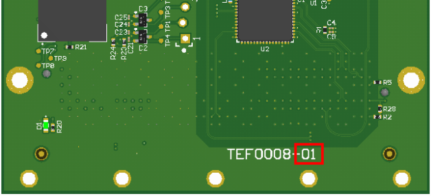
Figure 45: Module hardware revision number.
...
Date | Revision | Contributors | Description | ||||||||
|---|---|---|---|---|---|---|---|---|---|---|---|
| Author Name | What changed? | |||||||||
| Martin Rohrmüller | Initial document. | |||||||||
all | Jan Kumann, John Hartfiel |
Table 18: Document change history.
...
Overview
Content Tools