...
| Scroll pdf ignore |
|---|
Table of Contents |
Overview
| HTML |
|---|
<!--
Wiki Link: Go to Base Folder of the Module or Carrier, for example : https://wiki.trenz-electronic.de/display/PD/TE0712
--> |
| Scroll Only (inline) |
|---|
Refer to https://wiki.trenz-electronic.de/display/PD/TEB0911+TRM for the current online version of this manual and other available documentation.
|
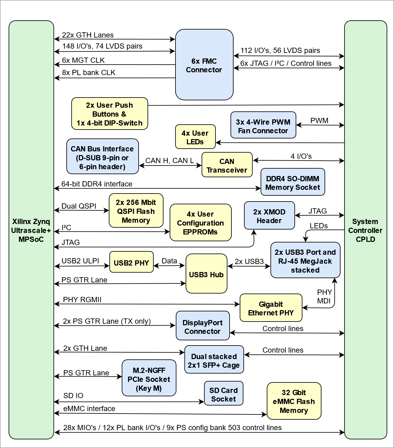
The Trenz Electronic TEB0911 UltraRack+ board is integrating a Xilinx Zynq Ultrascale+ MPSoC with 4 GByte Flash memory for configuration and operation, DDR4-SDRAM SO-DIMM socket with 64-bit wide data bus, 22 MGT lanes and powerful switch-mode power supplies for all on-board voltages.. The TEB0911 board exposes the pins of the Zynq MPSoC to accessible connectors and provides a whole range of on-board components to test and evaluate the Zynq Ultrascale+ MPSoC and for developing purposes. The board is capable to be fitted to a enclosure, whereby on the enclosure's rear and front panel, I/O's, LVDS-pairs and MGT lanes are accessible through 6 on-board FMC connectors and other standard high-speed interfaces, namely USB3, SFP+, SSD, GbE, etc.
| HTML |
|---|
<!--
Use short link the Wiki Ressource page: for example:
http://trenz.org/te0720-info
List of available short links: https://wiki.trenz-electronic.de/display/CON/Redirects
--> |
| Scroll Only (inline) |
|---|
Refer to http://trenz.org/teb0911-info for the current online version of this manual and other available documentation.
|
Key Features
- Single 24V main power supply
- 2x USB3 A Connector (Superspeed Host Port (Highspeed in USB2 mode))
- Gigabit Ethernet RGMII PHY with RJ45 MegJack
- Dual SFP+ Connector (2x1 Cage)
- DDR4-SDRAM SO-DIMM socket (64bit bus width)
- SSD (Solid State Disk) PCIe connector
- CAN FD interface (D-SUB 9-pin male connector and 6-pin header)
- DisplayPort (2 lanes)
- 4x On-board configuration EEPROMs (1x Microchip 24LC128-I/ST, 3x Microchip 24AA025E48T-I/OT)
- All carrier board peripherals' I²C interfaces muxed to MPSoC's I²C interface
- 6x FMC connectors
- 6x FMC Fans
- 3x 4-wire PWM fan connectors
- 10 output programmable PLL clock generator Si5345A
- Quad programmable PLL clock generator SI5338A
- 1x SMA coaxial connector for reference clock signal input
- SD Card socket (bootable)
- 32 Gbit (4 GByte) on-board eMMC flash (8 banks a 4 Gbit)
- System Controller CPLD Lattice MachXO2 7000 HC
- 2x XMOD header for programming MPSoC and SC CPLD
- On-board DC-DC PowerSoCs and LDOs
...
| Scroll Title |
|---|
| anchor | Figure_1 |
|---|
| title | Figure 1: TEB0911-03 block diagram |
|---|
|
| Scroll Ignore |
|---|
| draw.io Diagram |
|---|
| border | false |
|---|
| viewerToolbar | true |
|---|
| |
|---|
| fitWindow | false |
|---|
| diagramName | TEB0911 block diagram |
|---|
| simpleViewer | false |
|---|
| width | |
|---|
| links | auto |
|---|
| tbstyle | hidden |
|---|
| lbox | true |
|---|
| diagramWidth | 641 |
|---|
| revision | 2021 |
|---|
|
|
| Scroll Only |
|---|
|
|
Main Components
...