Page History
...
| Scroll Title | ||||||||||||||||||||||||||||||||||||
|---|---|---|---|---|---|---|---|---|---|---|---|---|---|---|---|---|---|---|---|---|---|---|---|---|---|---|---|---|---|---|---|---|---|---|---|---|
| ||||||||||||||||||||||||||||||||||||
|

Main Components
| Scroll Title | ||||||||||||||||||||||||||||||||||||||||||||||||||||||||||||||||
|---|---|---|---|---|---|---|---|---|---|---|---|---|---|---|---|---|---|---|---|---|---|---|---|---|---|---|---|---|---|---|---|---|---|---|---|---|---|---|---|---|---|---|---|---|---|---|---|---|---|---|---|---|---|---|---|---|---|---|---|---|---|---|---|---|
| ||||||||||||||||||||||||||||||||||||||||||||||||||||||||||||||||
|
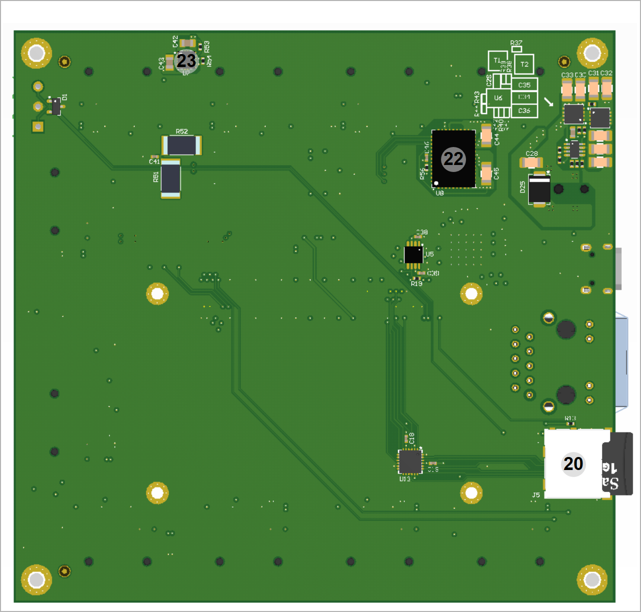
Table 1: TE0724-01 main components.
- Module connector for 4,0x6.0 cm module
- Pmods usabel as dual Pmods, J10, J11, J12, J13, J14, J15, J16, J17
- Pmod (single), J20
- I2C Pmod, J21
- CAN screw terminal, J2
- 5V 2.1mm input jack, J18
- microUSB J4
- USB to JTAG/UART bridge FT2232H, U1
- Configuration EEPROM U3
- RJ45 Gigabit Ehternet Jack, J3
- Power Button, S1
- Resetreq Reset Button, S3
- User Button PS, S5
- User LED (green) PS, D8
- 2x User Button PL, S2, S4
- 6x User LEDs (red) PL, D2-D7
- Power LED (green), D36
- 2x10 Pin header for Boot and Programming options, J6
- microSD Card Slot, J5
Initial Delivery State
...
For selection of the bootdevice the Pins
...
High or open
...
SD Card
...
Low or ground
...
QSPI Interface
mode jumpers on the pin header J6 are used. Placing a jumper at pin 13-14 sets Mode0 to low level. Mode1 is set to low level by a jumper on 15 -16. Boot modes are further described at the corresponding section of the used module, e.g. Table 2, Boot mode selection of TE0724 TRM. Default without jumpers is boot from SD-Card.
Table 2: Selecting power-on boot device.
Signals, Interfaces and Pins
...
I/O signals connected to the SoCs I/O bank and B2B connector:
...
| B2B Connector |
|---|
Table x: General overview of PL I/O signals connected to the B2B connectors.
All PS MIO banks are powered by on-module DC-DC power rail. All PL I/O banks have separate VCCO input pins in the B2B connectors, valid VCCO should be supplied from the carrier board.
For detailed information about the pin out, please refer to the Pin-out Tables.
The configuration of the PS I/Os MIOx, MIOx ... MIOx, ... depend on the carrier board peripherals connected to these pins.
| Interfaces | Count of IO's | Notes | |
|---|---|---|---|
| J1 | User IO | 72 single ended or 36 differential | 9x Pmod |
| 6 LED | red | ||
| 2 Push Button | - | ||
| 7 MIO | J7 (not assembled), TE0724: 3.3V | ||
| 2 MIO | J9 (not assembled), TE0724: 1.8V | ||
| 1 MIO LED | green | ||
| 1 MIO Push Button | - | ||
| I²C | 2 | 1x Pmod | |
| SD IO | 7 | - | |
| UART | 2 | - | |
| CAN | 2 | - | |
| GbE PHY_MDIO + PHY_LEDs | 10 | - | |
| JTAG | 4 | - | |
| Power GPIO | 2 | - | |
| Power/Reset/Fuse programming | 3 | - | |
| Bootmode | 2 | - |
Table 2: General overview of PL I/O signals and SoM's interfaces connected to the B2B connectors.
The TEB0724 carrier board supplies the attached module with 5V DC. All power rails are generated from this at the module and are routed back the carrier. For detailed information about the pin out, please refer to the Pin-out Tables.
| HTML |
|---|
<!--
TO-DO (future):
If Vivado board part files |
| HTML |
<!--
TO-DO (future):
If Vivado board part files are available for this module, the standard configuration of the MIO pins by using this board part files should be mentioned here. This standard configuration of those pins are also apparent of the on-board peripherals of base-boards related to the module.
--> |
MGT Lanes
| HTML |
|---|
<!--
MGT lanes should be listed separately, as they are more specific than just general I/Os.
--> |
MGT (Multi Gigabit Transceiver) lane consists of one transmit and one receive (TX/RX) differential pairs, two signals each or four signals total per one MGT lane. Following table lists lane number, MGT bank number, transceiver type, signal schematic name, board-to-board pin connection and FPGA pins connection:
...
- MGT_RX0_P
- MGT_RX0_N
- MGT_TX0_P
- MGT_TX0_N
...
- JM3-8
- JM3-10
- JM3-7
- JM3-9
...
- MGTHRXP0_225, Y2
- MGTHRXN0_225, Y1
- MGTHTXP0_225, AA4
- MGTHTXN0_225, AA3
...
- MGT_RX1_P
- MGT_RX1_N
- MGT_TX1_P
- MGT_TX1_N
...
- JM3-14
- JM3-16
- JM3-13
- JM3-15
...
- MGTHRXP1_225, V2
- MGTHRXN1_225, V1
- MGTHTXP1_225, W4
- MGTHTXN1_225, W3
...
- MGT_RX4_P
- MGT_RX4_N
- MGT_TX4_P
- MGT_TX4_N
...
- JM1-12
- JM1-10
- JM1-6
- JM1-4
...
- MGTHRXP0_224, AH2
- MGTHRXN0_224, AH1
- MGTHTXP0_224, AG4
- MGTHTXN0_224, AG3
...
- MGT_RX5_P
- MGT_RX5_N
- MGT_TX5_P
- MGT_TX5_N
...
- JM1-24
- JM1-22
- JM1-18
- JM1-16
...
- MGTHRXP1_224, AF2
- MGTHRXN1_224, AF1
- MGTHTXP1_224, AF6
- MGTHTXN1_224, AF5
...
JTAG Interface
JTAG access to the module is provided through B2B connector J1
JTAG Signal | B2B Connector Pin |
|---|---|
| TCK | J1-147 |
| TDI | J1-151 |
| TDO | J1-145 |
| TMS | J1-149 |
Table 3: JTAG interface signals.
System Control I/O Pins
| Pin Name | Mode | Function | B2B Connector Pin | Default Configuration |
|---|---|---|---|---|
| .. | .. | .. | .. | .. |
Table 4: System Controller CPLD I/O pins.
| HTML |
|---|
<!--
For the detailed function of the pins and signals, the internal signal assignment and implemented logic, look to the Wiki reference page SC CPLD of this module or into the bitstream file of the SC CPLD.
Add link to the Wiki reference page of the SC CPLD, if available.
--> |
SD Card Interface
| Connected To | Signal Name | Notes |
|---|---|---|
| J1-34 | SD-CD | Card detect switch |
| J1-24 | SD-D0 | |
| J1-22 | SD-CMD | |
| J1-20 | SD-CCLK | |
| J1-26 | SD-D1 | |
| J1-28 | SD-D2 | |
| J1-30 | SD-D3 |
Table 5: SD Card interface signals and connections.
Ethernet Interface
On board Gigabit Ethernet PHY is provided with ...
Ethernet PHY connection
| PHY Pin | PS | PL | B2B | Notes |
|---|---|---|---|---|
Table x: ...
I2C Interface
On-board I2C bus is connected to the following pins:
| SDA | SCL | Notes |
|---|---|---|
| J1-144 | J1-142 | B2B |
| J6-7 | J6-5 | In-Circuit Programming |
| J21-10, J21-4 | J21-9, J21-3 | PMOD |
Table x: I2C slave device addresses.
On-board Peripherals
| HTML |
|---|
<!--
Components on the Module, like Flash, PLL, PHY...
--> |
Gigabit Ethernet PHY
On-board Gigabit Ethernet PHY (U7) is provided with Marvell Alaska 88E1512 IC (U8). The Ethernet PHY RGMII interface is connected to the Zynq Ethernet0 PS GEM0. I/O voltage is fixed at 1.8V for HSTL signaling. The reference clock input of the PHY is supplied from an on-board 25.000000 MHz oscillator (U9), the 125MHz output clock signal CLK_125MHZ is connected to the pin J2-150 of B2B connector J2
Table x: MGT lanes.
Below are listed MGT banks reference clock sources.
...
Table x: MGT reference clock sources.
JTAG Interface
JTAG access to the ... is provided through B2B connector ....
...
JTAG Signal
...
B2B Connector Pin
...
Table 5: JTAG interface signals.
System Controller CPLD I/O Pins
Special purpose pins are connected to smaller System Controller CPLD and have following default configuration:
...
Table x: System Controller CPLD I/O pins.
| HTML |
|---|
<!--
For the detailed function of the pins and signals, the internal signal assignment and implemented logic, look to the Wiki reference page SC CPLD of this module or into the bitstream file of the SC CPLD.
Add link to the Wiki reference page of the SC CPLD, if available.
--> |
Quad SPI Interface
Following line is just an example, change it to your needs.
Quad SPI Flash (U14) is connected to the Zynq PS QSPI0 interface via PS MIO bank 500, pins MIO1 ... MIO6.
Note that table column says "Signal Name", it should match the name used on the schematic.
...
Table x: Quad SPI interface signals and connections.
SD Card Interface
Describe SD Card interface shortly here if the module has one...
...
Table x: SD Card interface signals and connections.
Ethernet Interface
On board Gigabit Ethernet PHY is provided with ...
Ethernet PHY connection
...
Table x: ...
USB Interface
USB PHY is provided with ...
...
Table x: ...
The schematic for the USB connector and required components is different depending on the USB usage. USB standard A or B connectors can be used for Host or Device modes. A Mini USB connector can be used for USB Device mode. A USB Micro connector can be used for Device mode, OTG Mode or Host Mode.
I2C Interface
On-board I2C devices are connected to MIO.. and MIO.. which are configured as I2C... by default. I2C addresses for on-board devices are listed in the table below:
...
Table x: I2C slave device addresses.
On-board Peripherals
| HTML |
|---|
<!--
Components on the Module, like Flash, PLL, PHY...
--> |
System Controller CPLD
The System Controller CPLD (U2) is provided by Lattice Semiconductor LCMXO2-256HC (MachXO2 Product Family). The SC-CPLD is the central system management unit where essential control signals are logically linked by the implemented logic in CPLD firmware, which generates output signals to control the system, the on-board peripherals and the interfaces. Interfaces like JTAG and I2C between the on-board peripherals and to the FPGA module are by-passed, forwarded and controlled by the System Controller CPLD.
Other tasks of the System Controller CPLD are the monitoring of the power-on sequence and to display the programming state of the FPGA module.
For detailed information, refer to the reference page of the SC CPLD firmware of this module.
| HTML |
|---|
<!--
Put in link to the Wiki reference page of the firmware of the SC CPLD.
--> |
DDR Memory
By default TE0xxx module has ... DDRx SDRAM chips arranged into 32-bit wide memory bus providing total of 1 GBytes of on-board RAM. Different memory sizes are available optionally.
Quad SPI Flash Memory
On-board QSPI flash memory (U14) on the TE0745-02 is provided by Micron Serial NOR Flash Memory N25Q256A with 256 Mbit (32 MByte) storage capacity. This non volatile memory is used to store initial FPGA configuration. Besides FPGA configuration, remaining free flash memory can be used for user application and data storage. All four SPI data lines are connected to the FPGA allowing x1, x2 or x4 data bus widths. Maximum data rate depends on the selected bus width and clock frequency used.
| Note |
|---|
SPI Flash QE (Quad Enable) bit must be set to high or FPGA is unable to load its configuration from flash during power-on. By default this bit is set to high at the manufacturing plant. |
Gigabit Ethernet PHY
On-board Gigabit Ethernet PHY (U7) is provided with Marvell Alaska 88E1512 IC (U8). The Ethernet PHY RGMII interface is connected to the Zynq Ethernet0 PS GEM0. I/O voltage is fixed at 1.8V for HSTL signaling. The reference clock input of the PHY is supplied from an on-board 25.000000 MHz oscillator (U9), the 125MHz output clock signal CLK_125MHZ is connected to the pin J2-150 of B2B connector J2.
High-speed USB ULPI PHY
Hi-speed USB ULPI PHY (U32) is provided with USB3320 from Microchip. The ULPI interface is connected to the Zynq PS USB0 via MIO28..39, bank 501 (see also section). The I/O voltage is fixed at 1.8V and PHY reference clock input is supplied from the on-board 52.000000 MHz oscillator (U33).
MAC Address EEPROM
A Microchip 24AA025E48 serial EEPROM (U23) contains a globally unique 48-bit node address, which is compatible with EUI-48(TM) specification. The device is organized as two blocks of 128 x 8-bit memory. One of the blocks stores the 48-bit node address and is write protected, the other block is available for application use. It is accessible over I2C bus with slave device address 0x53.
RTC - Real Time Clock
An temperature compensated Intersil ISL...
Programmable Clock Generator
There is a Silicon Labs I2C programmable quad PLL clock generator on-board (Si5338A, U2) to generate various reference clocks for the module.
...
IN1
...
-
...
Not used.
...
IN3
...
Reference input clock.
...
IN4
...
IN5
...
-
...
CLK0A
...
CLK1_P
...
FPGA bank 45.
...
CLK0_P
...
FPGA bank 45.
...
Table : Programmable quad PLL clock generator inputs and outputs.
Oscillators
The module has following reference clock signals provided by on-board oscillators and external source from carrier board:
...
Table : Reference clock signals.
On-board LEDs
| LED | Color |
|---|
| Signal | Description and Notes |
|---|---|
| D1 |
| green | VIN | power indicator | |
| D2-D7 | red | ULED1.. |
| 6 | User LED | ||
| D8 | green | MIO9 | MIO user LED |
Table : On-board LEDs.
Power and Power-On Sequence
...
Overview
Content Tools