Page History
...
| Module Model | Board Part Short Name | PCB Revision Support | DDR | QSPI Flash | Others | Notes |
|---|---|---|---|---|---|---|
| TE0720-03-2IF | TE0720_2IF | 03 | 1 GB | |||
Design supports following carriers:
| Carrier Model | Notes |
|---|---|
| TE0701-6 |
Additional HW Requirements:
| Additional Hardware | Notes |
|---|---|
| TEC0053-04 - EDPS Power Stage | https://shop.trenz-electronic.de/en/TEC0053-04-EDPS-Power-Stage?c=474 |
| BLDC Motor with mounted Encoder (1000SI) | https://shop.trenz-electronic.de/en/28170-BLDC-Motor-with-mounted-Encoder-1000SI?c=474 |
| Interchangeable Plug with four adapters and cable, 12V/2.5A | https://shop.trenz-electronic.de/en/28169-Interchangeable-Plug-with-four-adapters-and-cable-12V/2.5A?c=35 |
| 2x Pmod Cable Kit: 12-pin | https://shop.trenz-electronic.de/en/26742-Pmod-Cable-Kit-12-pin?c=37 |
| Pmod Cable Kit: 6 pin cable connector kit, 30 cm (12") in length | https://shop.trenz-electronic.de/en/25250-Pmod-Cable-Kit-6-pin-cable-connector-kit-30-cm-12-in-length?c=37 |
Content
| HTML |
|---|
<!-- Remove unused content --> |
...
Hardware Setup
Set TE0701-06 carrier board FMC_VADJ = 3.3V by switch S4:
S4 Setup S4_1 ON S4_2 ON S4_3 ON S4_4 OFF Set FMC_VADJ (set in step 1 to 3.3V) to drive both, the VIOTA and VIOTB by this arrangement of J16, J17 and J21.
Jumper Configuration J6 Short 1-2 J17 no connection J21 Short 2-3
VIOTA will provide 3.3V to PMOD J5 and FMC_VADJ will provide 3.3V to PMOD J6Set switch S3 of the TE0701-06 carrier board to:
S3 Setup S3_1 any S3_2 any S3_3 ON S3_4 OFF
S3_1 and S3_2 serve as general purpose pins connected to the CPLD on the TE0701-06.- IMPORTANT: Before connecting to TEC0053-04 by PMOD 12pin cables, power on the TE0701-06 (12V) and measure presence of the 3.3V voltage on the TE0701-06 PMOD J5 pin 12 and pin 6 and on the TE0701-06 PMOD J6 pin 12 and pin 6.
Connect TEC0053 to two 3.3V PMOD connectors on TE0701 carrier with two
Pmod 12-pin cables as shown in following image.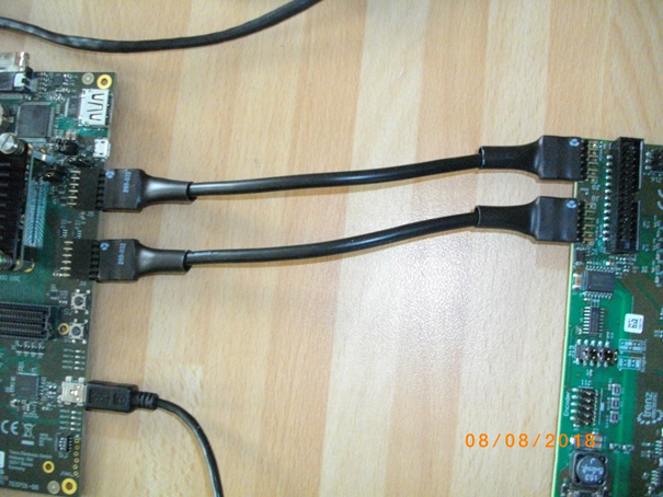
- Connect of motor rotation encoder as shown in following figure
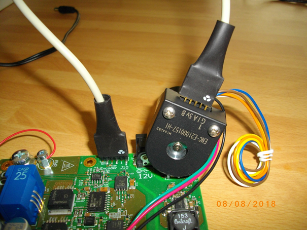
Motor rotation encoder is connected to the TEC0053-04 - EDPS Power Stage Pmod 6 pin cable connector kit. See the orientation and position of the 5 wire connection. There are 6 pins on the TEC0053-04 board. There are only 5 pins on the motor encoder. Pin 1 connects to pin 1. 6-th wire is unconnected on the motor encoder side.
3-phase of the motor phases are connected to the TEC0053-04 - EDPS Power Stage points A, B and C:
All other motor wires are unused.
A: green wire; B: red wire; C: black wire.
The TEC0053-04 - EDPS Power Stage can be powered by 12 V from the power supply by separate wire connecting of the point labled “PWR” (see above) with the fused point labled “+DC” (see the first picture).Description of connections of TE0701 with TEC0053-04
Code Block language perl # First PMOD cable 12-pin: # Connections of # TE0701-06 J5 with TEC0053 J9 set_property PACKAGE_PIN W18 [get_ports {SDV}]; #TE0701-06 J5:7 with TEC0053 J9:7 set_property PACKAGE_PIN W17 [get_ports {ENC_A}]; #TE0701-06 J5:8 with TEC0053 J9:8 set_property PACKAGE_PIN Y19 [get_ports {ENC_B}]; #TE0701-06 J5:9 with TEC0053 J9:9 set_property PACKAGE_PIN AA19 [get_ports {ENC_I}]; #TE0701-06 J5:10 with TEC0053 J9:10 # GND #TE0701-06 J5:11 with TEC0053 J9:11 # 3,3V #TE0701-06 J5:12 with TEC0053 J9:12 set_property PACKAGE_PIN Y16 [get_ports {SCLK}]; #TE0701-06 J5:1 with TEC0053 J9:1 set_property PACKAGE_PIN W16 [get_ports {SDI1}]; #TE0701-06 J5:2 with TEC0053 J9:2 set_property PACKAGE_PIN Y18 [get_ports {SDI2}]; #TE0701-06 J5:3 with TEC0053 J9:3 set_property PACKAGE_PIN AA18 [get_ports {SDI3}]; #TE0701-06 J5:4 with TEC0053 J9:4 #GND #TE0701-06 J5:5 with TEC0053 J9:5 #3,3V #TE0701-06 J5:6 with TEC0053 J9:6 #All signals connected by the first PMOD cable cable belong to TE0720 Zynq Bank 33. # Second PMOD cable 12-pin: # Connections of #TE0701-06 J6 with TEC0053 J8 set_property PACKAGE_PIN Y8 [get_ports {GL[0]}]; #TE0701-06 J6:7 with TEC0053 J8:7 set_property PACKAGE_PIN Y9 [get_ports {GL[1]}]; #TE0701-06 J6:8 with TEC0053 J8:8 set_property PACKAGE_PIN V9 [get_ports {GL[2]}]; #TE0701-06 J6:9 with TEC0053 J8:9 #GND #TE0701-06 J6:11 with TEC0053 J8:11 #3,3V #TE0701-06 J6:12 with TEC0053 J8:12 set_property PACKAGE_PIN AA7 [get_ports {GH[0]}]; #TE0701-06 J6:1 with TEC0053 J8:1 set_property PACKAGE_PIN AA6 [get_ports {GH[1]}]; #TE0701-06 J6:2 with TEC0053 J8:2 set_property PACKAGE_PIN U11 [get_ports {GH[2]}]; #TE0701-06 J6:3 with TEC0053 J8:3 #GND #TE0701-06 J6:5 with TEC0053 J8:5 #3,3V #TE0701-06 J6:6 with TEC0053 J8:6 # Second PMOD Cable 12-pin contains these two wires unconnected to the SDSoC design: #set_property PACKAGE_PIN V10 [get_ports {gpio_0_tri_io[0]}]; #TE0701-06 J6:10 - TEC0053 J8:10 #set_property PACKAGE_PIN U12 [get_ports {gpio_0_tri_io[1]}]; #TE0701-06 J6:4 - TEC0053 J8:4 #All signals connected by the second Pmod cable belong to TE0720 Zynq Bank 13.Info title NOTE The older TE0701-04 or TE0701-05 carrier boards can be used with the identical platform, but
the setup for generation of 3.3V on the PMOD J5 and PMOD J6 is different. There is no S4 switch and the FMC_VADJ = 3.3 V needs to be set by switch S3. Set switch S3 of the TE0701-04 or TE0701-05 carrier board to: S3_1 OFF; S3_2 ON; S3_3 ON; S3_4 OFF
Arrange jumpers J17 and J21:
J17: [1,2,3] connect 1-2
J21: [1,2,3] connect 2-3
Fixed 3.3V will go to PMOD J5. FMC_VADJ will provide 3.3V to PMOD J6Before connecting to TEC0053-04 by PMOD 12pin cables, power on (12V) the TE0701-04 or the TE0701-05 carrier board and measure presence of the 3.3V voltage on the TE0701-06 PMOD J5 pin 12 on pin 6 and presence of the 3.3V voltage coming from the adjustable FMC_VADJ on the TE0701-04 or TE0701-05 PMOD J6 pin 12 and pin 6.
Design Setup
Launch
References
...
| Include Page | ||||
|---|---|---|---|---|
|
# First PMOD cable 12-pin:
# Connections of # TE0701-06 J5 with TEC0053 J9
set_property PACKAGE_PIN W18 [get_ports {SDV}]; # TE0701-06 J5:7 with TEC0053 J9:7
set_property PACKAGE_PIN W17 [get_ports {ENC_A}]; # TE0701-06 J5:8 with TEC0053 J9:8
set_property PACKAGE_PIN Y19 [get_ports {ENC_B}]; # TE0701-06 J5:9 with TEC0053 J9:9
set_property PACKAGE_PIN AA19 [get_ports {ENC_I}]; # TE0701-06 J5:10 with TEC0053 J9:10
# GND # TE0701-06 J5:11 with TEC0053 J9:11
# 3,3V #TE0701-06 J5:12 with TEC0053 J9:12 set_property PACKAGE_PIN Y16 [get_ports {SCLK}]; #TE0701-06 J5:1 with TEC0053 J9:1
set_property PACKAGE_PIN W16 [get_ports {SDI1}]; #TE0701-06 J5:2 with TEC0053 J9:2
set_property PACKAGE_PIN Y18 [get_ports {SDI2}]; #TE0701-06 J5:3 with TEC0053 J9:3
set_property PACKAGE_PIN AA18 [get_ports {SDI3}]; #TE0701-06 J5:4 with TEC0053 J9:4
#GND #TE0701-06 J5:5 with TEC0053 J9:5
#3,3V #TE0701-06 J5:6 with TEC0053 J9:6
#All signals connected by the first PMOD cable cable belong to TE0720 Zynq Bank 33.
# Second PMOD cable 12-pin:
# Connections of #TE0701-06 J6 with TEC0053 J8
set_property PACKAGE_PIN Y8 [get_ports {GL[0]}]; #TE0701-06 J6:7 with TEC0053 J8:7
set_property PACKAGE_PIN Y9 [get_ports {GL[1]}]; #TE0701-06 J6:8 with TEC0053 J8:8
set_property PACKAGE_PIN V9 [get_ports {GL[2]}]; #TE0701-06 J6:9 with TEC0053 J8:9
#GND #TE0701-06 J6:11 with TEC0053 J8:11
#3,3V #TE0701-06 J6:12 with TEC0053 J8:12
set_property PACKAGE_PIN AA7 [get_ports {GH[0]}]; #TE0701-06 J6:1 with TEC0053 J8:1
set_property PACKAGE_PIN AA6 [get_ports {GH[1]}]; #TE0701-06 J6:2 with TEC0053 J8:2 set_property PACKAGE_PIN U11 [get_ports {GH[2]}]; #TE0701-06 J6:3 with TEC0053 J8:3 #GND #TE0701-06 J6:5 with TEC0053 J8:5
#3,3V #TE0701-06 J6:6 with TEC0053 J8:6
# Second PMOD Cable 12-pin contains these two wires unconnected to the SDSoC design:
#set_property PACKAGE_PIN V10 [get_ports {gpio_0_tri_io[0]}]; #TE0701-06 J6:10 - TEC0053 J8:10
#set_property PACKAGE_PIN U12 [get_ports {gpio_0_tri_io[1]}]; #TE0701-06 J6:4 - TEC0053 J8:4
#All signals connected by the second Pmod cable belong to TE0720 Zynq Bank 13.
Overview
Content Tools