Page History
...
| Module Model | Board Part Short Name | PCB Revision Support | DDR | QSPI Flash | Others | Notes |
|---|---|---|---|---|---|---|
| TE0720-03-2IF | TE0720_2IF | REV03 | 1 GB | 32 | ||
| TE0720-03-l1if | TE0720-L1IF | REV03 | 512MB (L) | 32 | ||
| TE0720-03-1CF | TE0720-1CF | REV03 | 1 GB | 32 | ||
| TE0720-03-2EF | TE0720-2EF | REV03 | 1 GB | 32 | ||
| TE0720-03-07S | TE0720-07S | REV03 | 1 GB (L) | 32 |
Design supports following carriers:
| Carrier Model | Notes |
|---|---|
| TE0706-2 |
Additional HW Requirements:
Content
| HTML |
|---|
<!-- Remove unused content --> |
...
Hardware Setup
On TE0706-02 carrier board, use jumpers J10, J11 and J12 to select 3.3V:
Jumper Settings J10 Short 2-3 J11 Short 2-3 J12 Short 2-3 On TE0706-02 carrier board, set switch S1 to:
Switch Settings S1_1 OFF S1_2 OFF S1_3 OFF S1_4 ON On TE0790-02 XMOD FTDI JTAG Adapter of the TE0706-02 board, set switch S2 to:
Switch Settings S2_1 ON S2_2 OFF S2_3 ON S2_4 OFF Info title IMPORTANT Before connecting to TEC0053-04 by PMOD 12pin cables, power on the TE0706-02 (NOTE: 5V!) and measure presence of 3.3V voltage on the TE0706-02 connector J5 pins: J5:5, J5:6, J5:45, J5:46.
Connection of motor rotation encoder
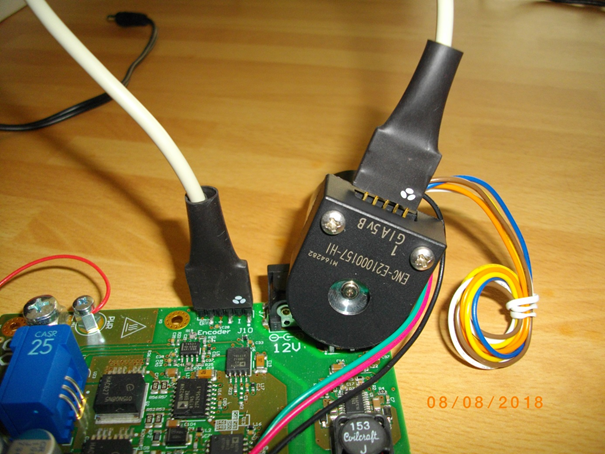
Motor rotation encoder is connected to the TEC0053-04 - EDPS Power Stage Pmod 6 pin cable connector kit. See the orientation and position of the 5 wire connection. There are 6 pins on the TEC0053-04 board. There are only 5 pins on the motor encoder. Pin 1 connects to pin 1. 6-th wire is unconnected on the motor encoder side.
3-phase of the motor phase wires are connected to the TEC0053-04 Power Stage points A, B, C: A: green wire; B: red wire; C: black wire.
All other motor wires are unused.
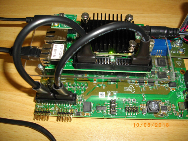
The TEC0053-04 - EDPS Power Stage can be powered by 12 V from the power supply by separate wire connecting of the point labled “PWR” (see above) with the fused point labeled “+DC” (see the first picture).Connect TE0706 with TEC0053-04 by two PMOD 12-pin cables.
Code Block language perl title Description of connections of TE0706 with TEC0053-04 # First 12 pin PMOD cable # Connections of TEC0053 J17 with TE0706-02 J5 # TEC0053 # TE0706-02 # GND # J17:25 # J5:50 set_property PACKAGE_PIN G20 [get_ports {SCLK}]; # J17:23 # J5:48 # 3,3V # J17:21 # J5:46 set_property PACKAGE_PIN E21 [get_ports {SDI1}]; # J17:19 # J5:44 set_property PACKAGE_PIN B19 [get_ports {SDI2}]; # J17:17 # J5:42 set_property PACKAGE_PIN D20 [get_ports {SDI3}]; # J17:15 # J5:40 # GND # J17:26 # J5:49 set_property PACKAGE_PIN G21 [get_ports {SDV}]; # J17:24 # J5:47 # 3,3V # J17:22 # J5:45 set_property PACKAGE_PIN D21 [get_ports {ENC_A}]; # J17:20 # J5:43 set_property PACKAGE_PIN B20 [get_ports {ENC_B}]; # J17:18 # J5:41 set_property PACKAGE_PIN C20 [get_ports {ENC_I}]; # J17:16 # J5:39 # All signals connected by the first PMOD cable cable belong to TE0720 Zynq Bank 35. # Second 12 pin PMOD cable # Connections of TEC0053 J17 with TE0706-02 J5 # TEC0053 # TE0706-02 # GND # J17:1 # J5:2 # Not used in the design # J17:3 # J5:4 # 3,3V # J17:5 # J5:6 set_property PACKAGE_PIN W17 [get_ports {GH[2]}]; # J17:7 # J5:8 set_property PACKAGE_PIN W20 [get_ports {GH[1]}]; # J17:9 # J5:10 set_property PACKAGE_PIN AA16 [get_ports {GH[0]}]; # J17:11 # J5:12 # GND # J17:2 # J5:1 # Not used in the design # J17:4 # J5:3 # 3,3V # J17:6 # J5:5 set_property PACKAGE_PIN W18 [get_ports {GL[2]}]; # J17:8 # J5:7 set_property PACKAGE_PIN W21 [get_ports {GL[1]}]; # J17:10 # J5:9 set_property PACKAGE_PIN AB16 [get_ports {GL[0]}]; # J17:12 # J5:11 #All signals connected by the second PMOD cable belong to TE0720 Zynq Bank 33. # Second PMOD Cable 12-pin contains these two wires unconnected to the SDSoC design: # Unused connections of TEC0053 J17 with TE0706-02 J5 # TEC0053 # TE0706-02 #set_property PACKAGE_PIN W16 [get_ports {gpio_0_tri_io[1]}]; # J17:3 # J5:4 #set_property PACKAGE_PIN Y16 [get_ports {gpio_0_tri_io[0]}]; # J17:4 #J5:3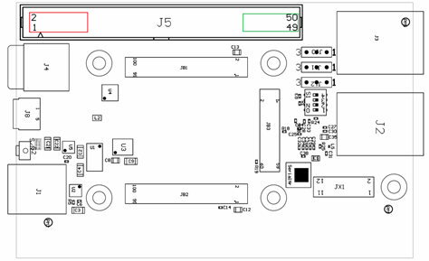
TE0706-02 carrier board has highlighted position of two 12 pin PMOD cables. Please take care, when connecting both cables to respect pin connections as listed above.
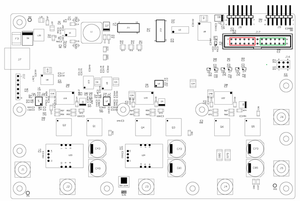
TEC0053-04 power stage board has highlighted position of two 12 pin PMOD cables.Info title IMPORTANT Wrong placement of the PMOD 12pin connects might result in a damaged electronic.
Design Setup
Launch
References
...
Overview
Content Tools