...
Trenz Electronic TE0728 is an automotive-grade FPGA module integrating an Automotive Xilinx Zynq-7 FPGA, two 100 Mbit Ethernet transceivers (PHY) , 512 MByte DDR3L SDRAM, 16 MByte QSPI Flash memory for configuration and operation, and powerful switching-mode power supplies for all on-board voltages. Numerous configurable I/Os are provided via rugged high-speed strips.
...
- Xilinx XA7Z020-1CLG484Q (Automotive) [Z7014S is available on demand]
- Rugged for shock and high vibration
- Dimensions: 6 x 6 cm
- Temperature range: Automotive
- Dual-Core ARM Cortex-A9 MPCore
- 2 x 100 MBit Ethernet transceiver (PHY)
- DDR3L SDRAM, 16-bit-width [ ]
- QSPI Flash memory (with XiP support) [ ]
- Plug-on module with 3 x 80-pin Samtec Micro Tiger Eye(TM) high-speed connectors
- 76 single ended I/O, 24 LVDS pairs (48 I/O) and 42 MIO available on board-to-board connectors
- CAN transceiver (PHY)
- 12 V power supply with watchdog
- On-board high-efficiency DC-DC converters
- System management and power sequencing
- eFUSE bit-stream encryption
- AES bit-stream encryption
- Temperature compensated RTC (real-time clock)
- Three user LEDs
- Evenly-spread supply pins for good signal integrity
...
| Scroll Title |
|---|
| anchor | Figure_OV_BD |
|---|
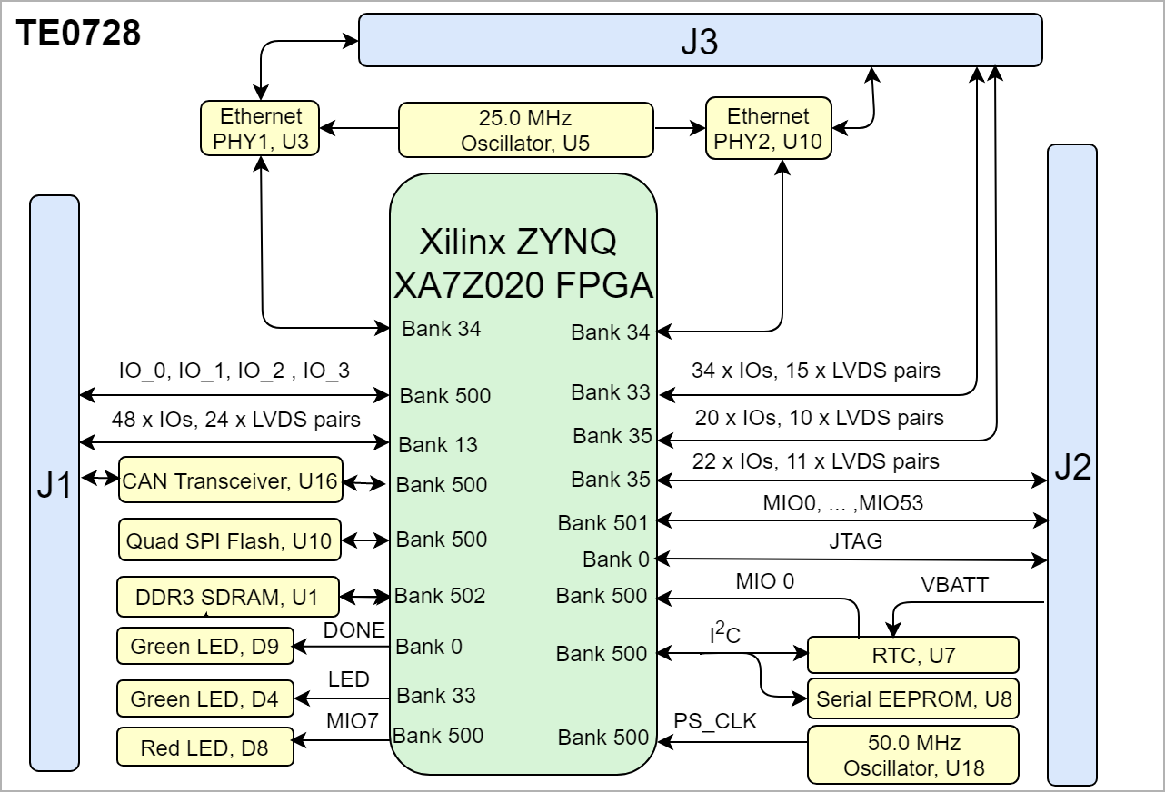
| title | TE0728 block diagram |
|---|
|
| Scroll Ignore |
|---|
| draw.io Diagram |
|---|
| border | false |
|---|
| viewerToolbar | true |
|---|
| |
|---|
| fitWindow | false |
|---|
| diagramDisplayName | |
|---|
| lbox | true |
|---|
| revision | 1314 |
|---|
| diagramName | TE0728_OV_BD |
|---|
| simpleViewer | false |
|---|
| width | |
|---|
| links | auto |
|---|
| tbstyle | hidden |
|---|
| diagramWidth | 641 |
|---|
|
|
| Scroll Only |
|---|
|
|
...
- DDR3 SDRAM, U1
- Xilinx Automotive XA7Z020-1CLG484Q ,U2
- 100 MBit Ethernet transceiver, U3
- 100 MBit Ethernet transceiver, U10
- User LED Green, D4
- Real Time Clock, Micro Crystal @32.768 MHz, U7
- Standard Clock Oscillators @ 25MHz, U5
- 64 Kbit I2C EEPROM, U11
- CAN Tranceiver, U16
- QSPI Nor Flash memory, U13
- Standard Clock Oscillators @ 50MHz, U14
- Low-Quiescent-Current Programmable Delay Supervisory Circuit, U15
- Low-Quiescent-Current Proggrammable Programmable Delay Supervisory Circuit, U12
- B2B connector , JM2
- B2B connector , JM3
- B2B connector , JM1
...
| Scroll Title |
|---|
| anchor | Table_OV_IDS |
|---|
| title | Initial delivery state of programmable devices on the module |
|---|
|
| Scroll Table Layout |
|---|
| orientation | portrait |
|---|
| sortDirection | ASC |
|---|
| repeatTableHeaders | default |
|---|
| style | |
|---|
| widths | |
|---|
| sortByColumn | 1 |
|---|
| sortEnabled | false |
|---|
| cellHighlighting | true |
|---|
|
Storage Device | Symbol | Content |
|---|
Quad SPI Flash | U13 | Not Programmed | | EEPROM | U11 | Not Programmed |
|
Configuration Signals
| Page properties |
|---|
|
- Overview of Boot Mode, Reset, Enables,
|
Boot Mode
| Scroll Title |
|---|
| anchor | Table_OV_BP |
|---|
| title | Boot process. |
|---|
|
| Scroll Table Layout |
|---|
| orientation | portrait |
|---|
| sortDirection | ASC |
|---|
| repeatTableHeaders | default |
|---|
| style | |
|---|
| widths | |
|---|
| sortByColumn | 1 |
|---|
| sortEnabled | false |
|---|
| cellHighlighting | true |
|---|
|
Signal | FPGA Bank | Pin | B2B | Signal State | Boot Mode |
|---|
Boot_R | 500 | E4 | J2-11 | Low | QSPI | | High | SD Card |
|
Reset
Zynq-7020SoC includes a reset that is driven by the reset system. Hardware resets are driven by the power-on reset signal (Reset) connected to carrier and the system reset signal (PS_SRST_B) connected to VMIO, it means after power on the PS will be reset.
...
| Scroll Title |
|---|
| anchor | Table_SIP_B2B |
|---|
| title | General PL I/O to B2B connectors information |
|---|
|
| Scroll Table Layout |
|---|
| orientation | portrait |
|---|
| sortDirection | ASC |
|---|
| repeatTableHeaders | default |
|---|
| style | |
|---|
| widths | |
|---|
| sortByColumn | 1 |
|---|
| sortEnabled | false |
|---|
| cellHighlighting | true |
|---|
|
| FPGA Bank | Type | B2B Connector | I/O Signal Count | Voltage Level | Notes |
|---|
| 13 | HR | J1 | 48 (24)Single-end, 24 Diff | VCCO_13 | variable from carrier | | 500 | HR | J1 | 4 | 3.3V |
| | 501 | HR | J2 | 37 | VMIO1 | variable from carrier | | 33 | HR | J3 | 34 | 3.3V |
| | 35 | HR | J3 | 20 | 3.3V |
| | 35 | HR | J2 | 22 | 3.3V |
|
|
...