...
TEBF0808 with TE080x
Overview
Basic instructions to work with TEBF0808 and TE0808,TE0807 or TE0803.
| Info |
|---|
Functionality of buttons, DIP switches, LEDs depends on CPLD Firmware. Following description is only for newest firmware version, which is available on the download area |
| Scroll Title |
|---|
| anchor | Figure_Overview |
|---|
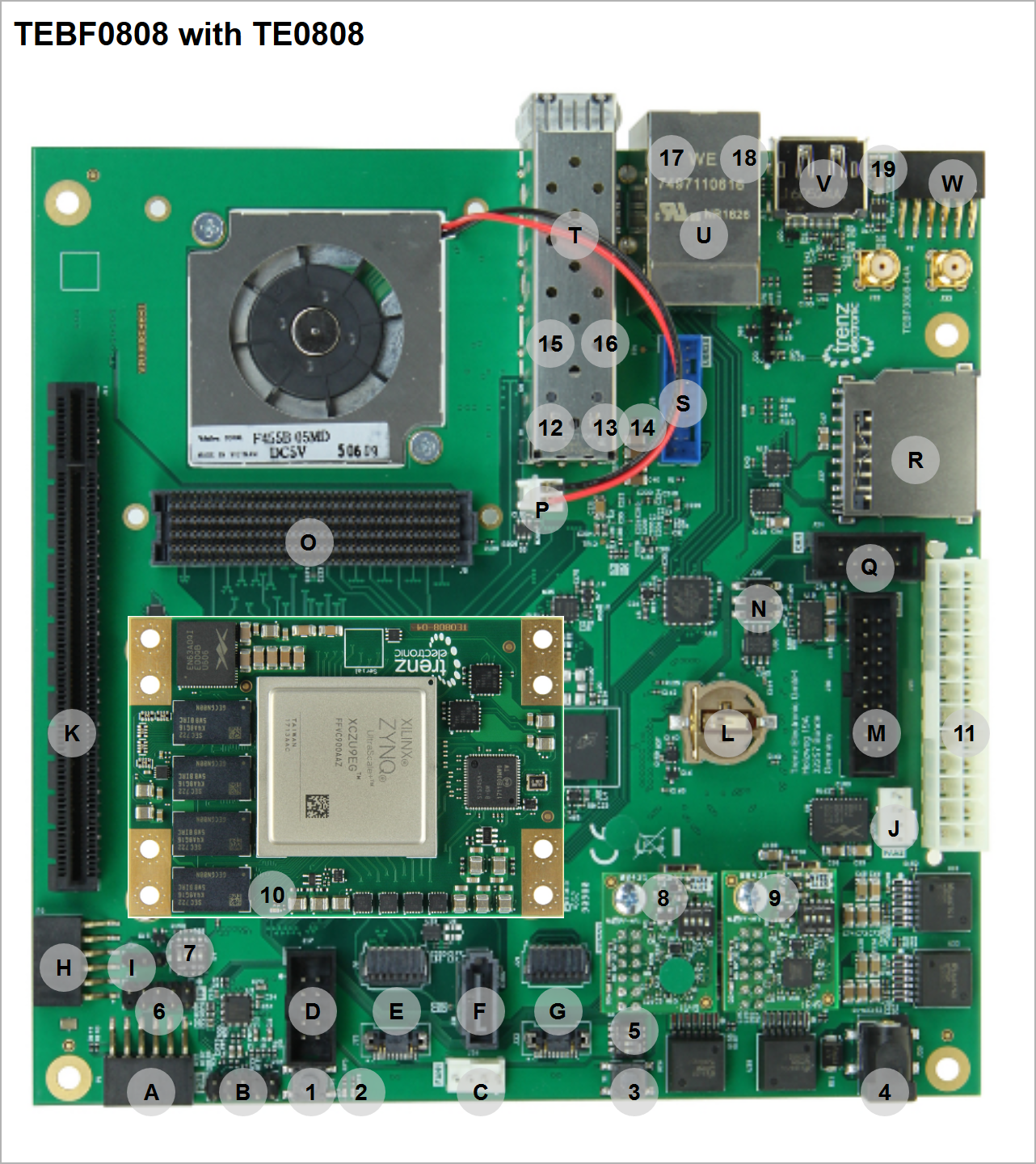
| title | Board Overview |
|---|
|
| Scroll Ignore |
|---|
| scroll-pdf | true |
|---|
| scroll-office | true |
|---|
| scroll-chm | true |
|---|
| scroll-docbook | true |
|---|
| scroll-eclipsehelp | true |
|---|
| scroll-epub | true |
|---|
| scroll-html | true |
|---|
| | draw.io Diagram |
|---|
| border | false |
|---|
| viewerToolbar | true |
|---|
| |
|---|
| fitWindow | false |
|---|
| diagramDisplayName | |
|---|
| lbox | true |
|---|
| revision | 35 |
|---|
| diagramName | TEBF0808_getting_started_overview |
|---|
| simpleViewer | true |
|---|
| width | |
|---|
| links | auto |
|---|
| tbstyle | top |
|---|
| diagramWidth | 641 |
|---|
|
|
| Scroll Only |
|---|
|
|
| Number | Note | Letter | Note |
|---|
| 1 | Reset Button S2 | A | PMOD 3.3V I2C |
| 2 | LEDs D7 Red (Usage: status) and D6 Green (Usage: status) | B |
|
| 3 | Reset Button S1 | C |
|
| 4 | Power Jack J25, 2.1mm (optional 12V power input) | D |
|
| 5 | S5 DIP for Boot Mode and FMCVADJ | E |
|
| 6 | Enclosure Pin header(Reset and Power Button, HD LED (Usage: status/user) and Power LED (Usage: status/user)) | F |
|
| 7 | S4 DIP for CPLD access and power control | G |
|
| 8 | XMOD J12 with green dot for Module JTAG and UART, XMOD LED D4 Red used for status information | H |
|
| 9 | XMOD J28 for CPLD,FMC JTAG and Firmware ID over UART(need CPLD Firmware 7 or newer) , XMOD LED D4 Red used for status information | I |
|
| 10 | FPGA Done LED (location varies slightly depending on module) | K |
|
| 11 | ATX Power Connector J20 (Main 12V and 5V Power supply), recommended power supply connector | L |
|
| 12 | SFP LED D1 Red (Usage: status/user) | M |
|
| 13 | SFP LED D8 Green (Usage: status/user) | N |
|
| 14 | SFP LED D9 Red (Usage: status/user) | O |
|
| 15 | SFP LED D10 Green (Usage: status/user) | P |
|
| 16 | ETH LED Yellow (Usage: status) | Q |
|
| 17 | ETH LED Green/Orange (Usage: status) |
|
|
| 18 | LEDs D4 Green (Usage: status/user) and D5 Red (Usage: status/user) |
|
|
Power supply
| Page properties |
|---|
|
The input power supply must be mentioned. Add Link to overview picture with connector label.
|
Recommended power supply unit is PC power supply unit over connector J20 (Overview - 12)
- DIP S4-4 can be switched OFF with this power supply configuration (CPLD firmware depended)
Optional single 12V power supply over J25 (Overview - 12)
- DIP S4-4 must be switched ON with this power supply
DIP-Switches and Push Buttons
...
| Scroll Title |
|---|
| anchor | Table_XMOD_JTAG |
|---|
| title | XMOD JTAG DIP Switch. Attention: Never changes the default setting |
|---|
|
| Scroll Table Layout |
|---|
| orientation | portrait |
|---|
| sortDirection | ASC |
|---|
| repeatTableHeaders | default |
|---|
| sortByColumn | 1 |
|---|
| sortEnabled | false |
|---|
| cellHighlighting | true |
|---|
|
| DIP Switch | Setting |
|---|
| 1 | ON | | 2 | OFF | | 3 | OFF | | 4 | OFF |
|
CPLD Firmware Update
Boot Mode
Reference Designs
| Page properties |
|---|
|
In this Section you must refer to the Reference Design (Test board) for the particular module. For Example: TE0728 Reference Designs |
...