Page History
...
| Scroll Title | ||||||||||||||||||||||||||||||||
|---|---|---|---|---|---|---|---|---|---|---|---|---|---|---|---|---|---|---|---|---|---|---|---|---|---|---|---|---|---|---|---|---|
| ||||||||||||||||||||||||||||||||
|
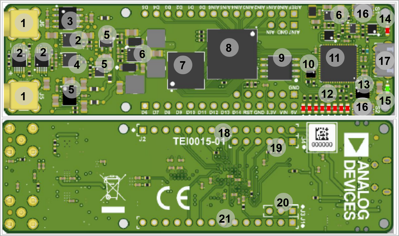
- SMA Connector, J5...6
- Instrumentation Amplifier, U12- U14- U6
- Series Voltage Reference, U8
- Analog to Digital Convertor, U15- U6
- Voltage Regulator, U10- U13- U16
- Buck Switching Voltage Regulator, U11- U4
- Intel® MAX 10, U1
- SDRAM Memory, U2
- SPI Flash Memory, U5
- Oscillator 12MHz12.00 MHz MEMS oscillator, U7
- FTDI USB USB2 to JTAG/UART convertoradapter, U3
- User LEDs, D2...9
- 4Kb EEPROM, U9
- Configuration LED (Red) , D10
- Power-on LED (Green), D1
- SwitchPush button, S1...2
- USB port, J9
- Micro USB2 socket (Receptacle), J9
- 1x14 pin header (Not assembled), J2
- 1x6 pin header (Not assembled), J4
- Jumper, J3
- 1x14 pin header Pin Holder (Not assembled), J1...4
Initial Delivery State
| Page properties | ||||
|---|---|---|---|---|
| ||||
Notes : Only components like EEPROM, QSPI flash and DDR3 can be initialized by default at manufacture. If there is no components which might have initial data ( possible on carrier) you must keep the table empty |
...
Overview
Content Tools