Page History
| Page properties | ||||
|---|---|---|---|---|
| ||||
Diese Seite wird verwaltet von der identischen Seite bei TEI0015 |
Table of Content
| Table of Contents |
|---|
Download
Compressed folder, containing all necessary files for the demo - Download-Link
The compressed folder needs to be extracted, so that the contend can be used inside other programs.
The demo itself requires the installation of Visual Analog (Version 1.9.48.1) - Download Link
2 Variants available:
- TEI0016-0x-08-C8A assembled with ADAQ7988BCCZ (500kS/s)
- TEI0016-0x-08-C8B assembled with ADAQ7980BCCZ (1MS/s)
| Excerpt Include | ||||||
|---|---|---|---|---|---|---|
|
FTDI EEPROM update
This is only needed once for rev -01 PCB boards from initial shipment!
...
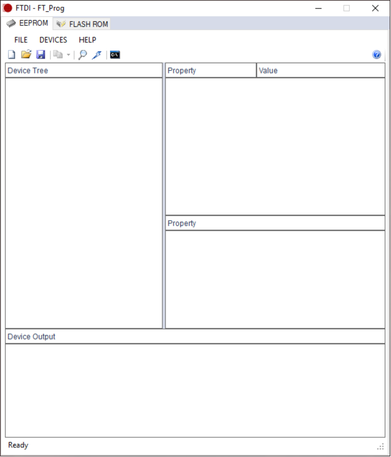
The window should look like TEI0016 Data capture Demo.
...
| anchor | Figure 1 |
|---|---|
| title | Figure 1: FT_Prog started |
...
| Scroll Only |
|---|
|
...
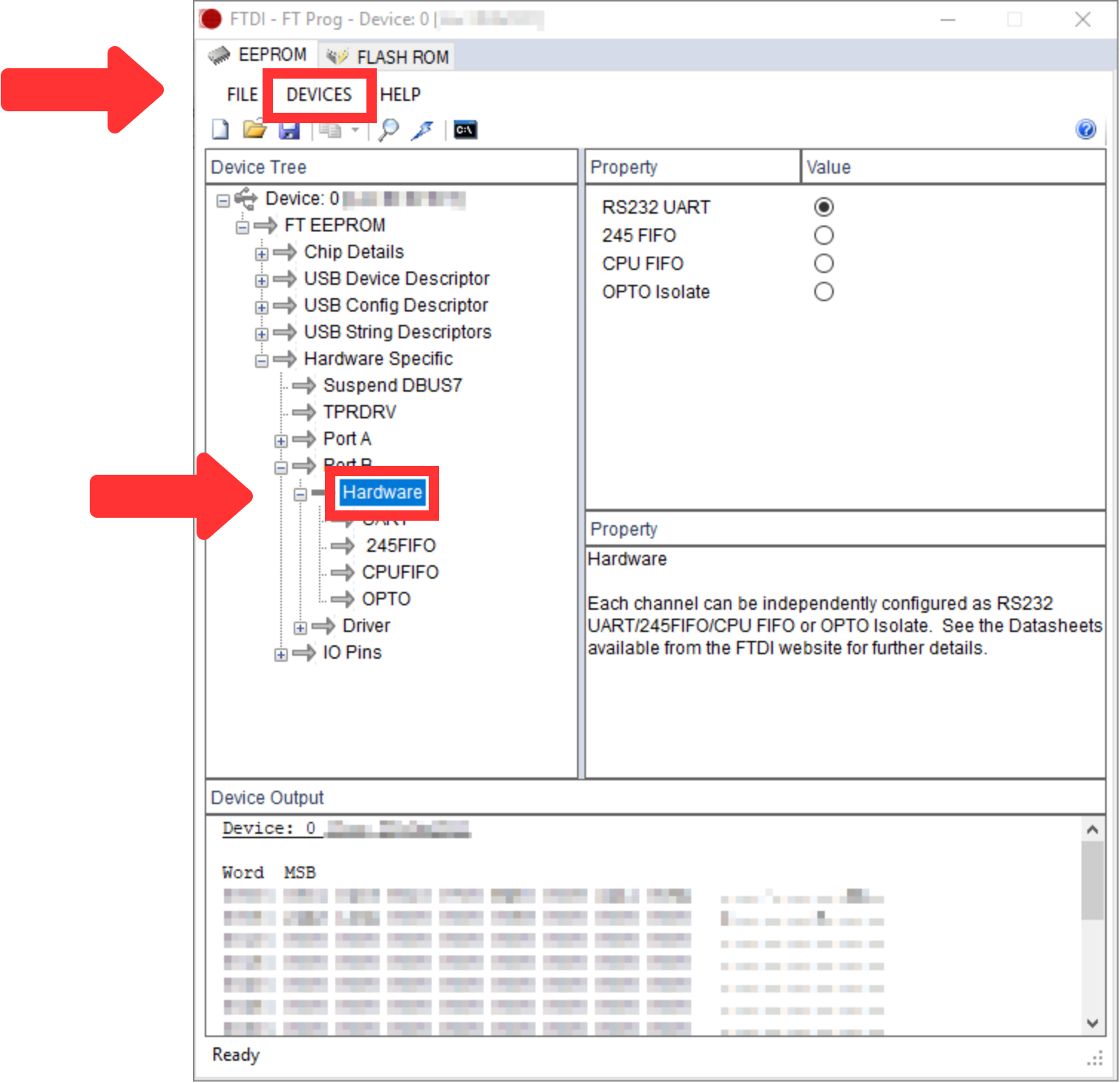
The window should look like TEI0016 Data capture Demo.
...
| anchor | Figure 2 |
|---|---|
| title | Figure 2: FT_Prog port scanned |
...
| Scroll Only |
|---|
|
...
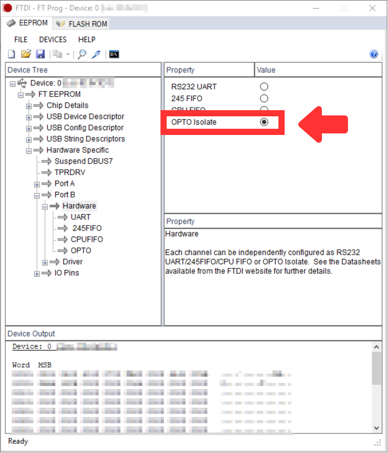
| anchor | Figure3 |
|---|---|
| title | Figure 3: FT_Prog "OPTO Isolate" selected |
...
| Scroll Only |
|---|
|
...
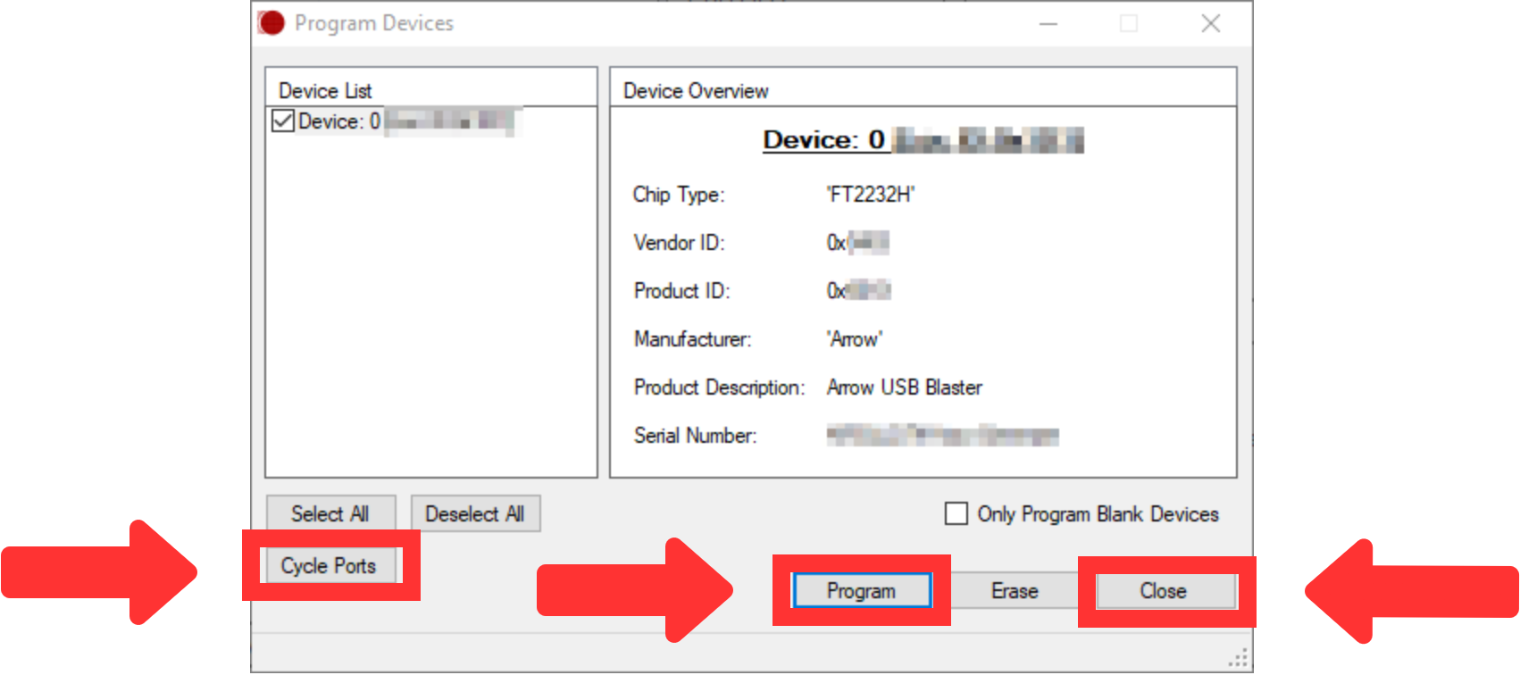
| anchor | Figure 4 |
|---|---|
| title | Figure 4: FT_Prog "Program Devices" |
...
| Scroll Only |
|---|
|
...
FPGA image update
...
| anchor | Figure 5 |
|---|---|
| title | Figure 5: Quartus Prime Programmer started |
...
| Scroll Only |
|---|
|
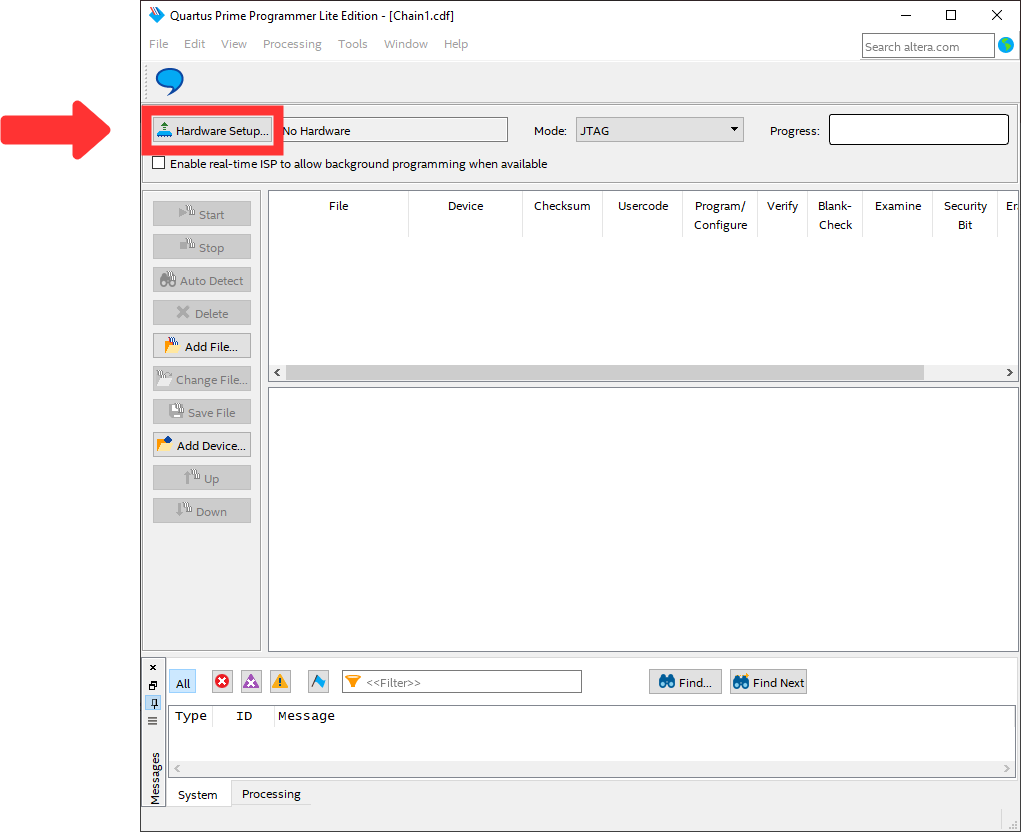
Press "Hardware Setup..." and select "Arrow-USB-Blaster [USBX]" in "Currently selected hardware" as visible in TEI0016 Data capture Demo, whereby the "X" in [USBX] is a placeholder.
...
| anchor | Figure 6 |
|---|---|
| title | Figure 6: Quartus Prime Programmer Hardware Setup |
...
| Scroll Only |
|---|
|
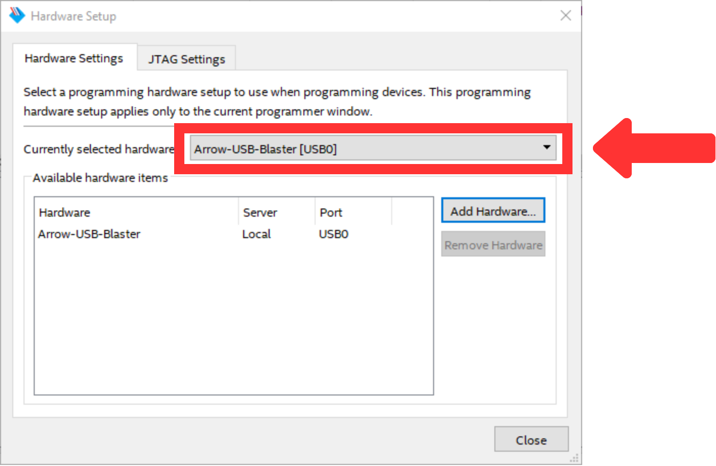
Then, press "Close" and return to the previous window. The window should look like TEI0016 Data capture Demo.
...
| anchor | Figure 7 |
|---|---|
| title | Figure 7: Quartus Prime Programmer Hardware Devices Setup |
...
| Scroll Only |
|---|
|
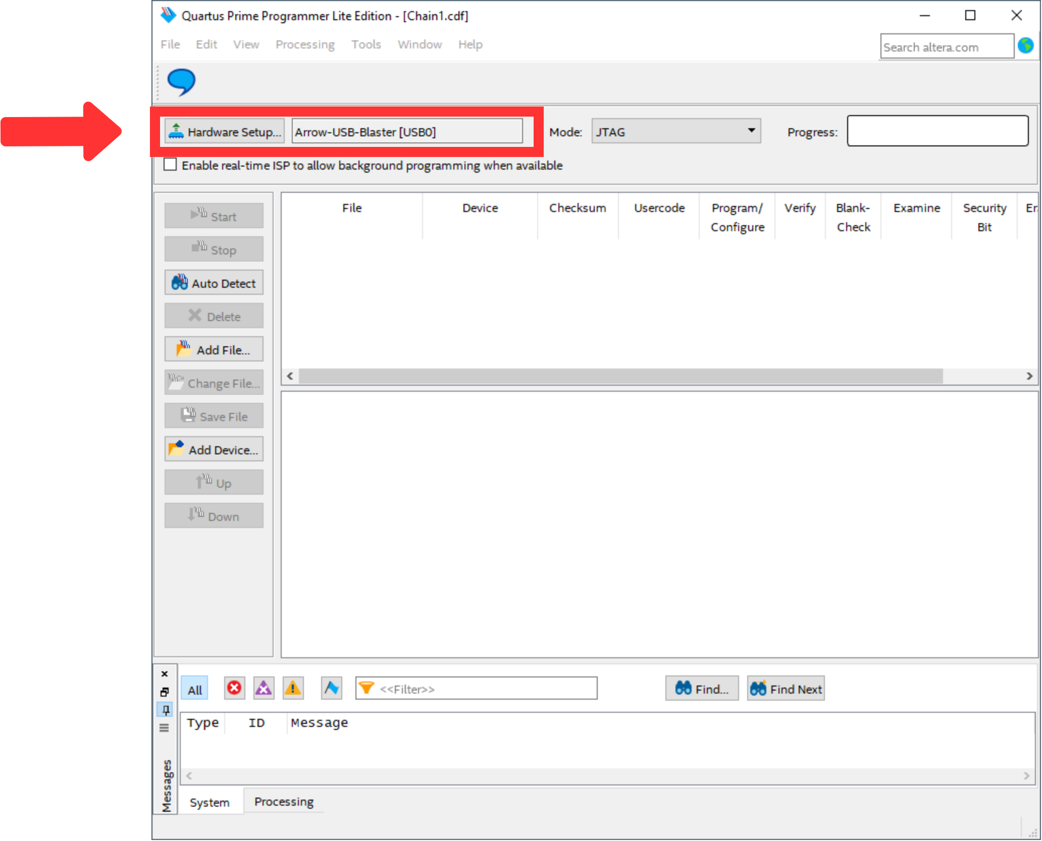
After that, use "Add File..." to select the file "TEI0016-01.pof" from the downloaded zip-file to program the FPGA. The window should look like TEI0016 Data capture Demo.
...
| anchor | Figure 8 |
|---|---|
| title | Figure 8: Quartus Prime Programmer POF selected |
...
| Scroll Only |
|---|
|
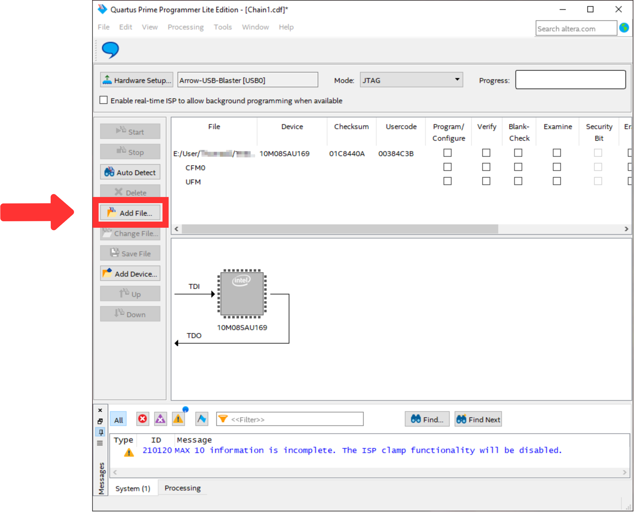
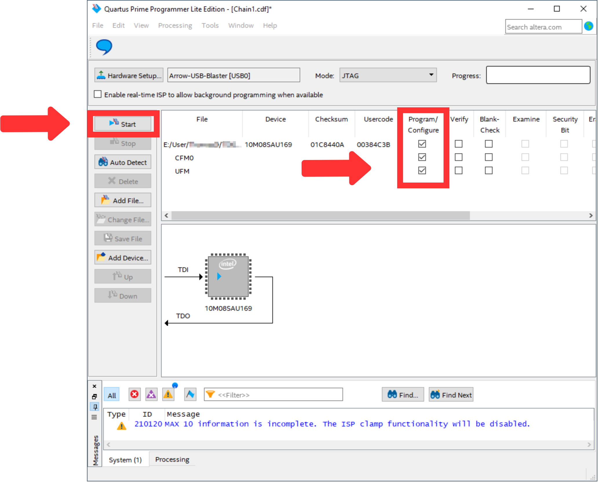
Mark the "Program/Configure" box for the selected file. Then, the window should look like TEI0016 Data capture Demo.
...
| anchor | Figure 9 |
|---|---|
| title | Figure 9: Quartus Prime Programmer POF selected |
...
| Scroll Only |
|---|
|
...
Integration with Visual Analog
...
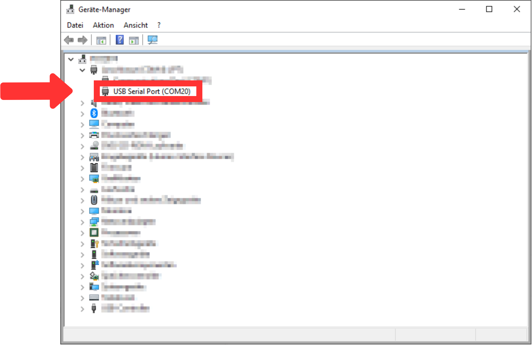
Open ports and identify the port used by the AnalogMAX DAQ2 as visible in TEI0016 Data capture Demo.
...
| anchor | Figure 10 |
|---|---|
| title | Figure 10: Device Manager for COM port identification |
...
| Scroll Only |
|---|
|
...
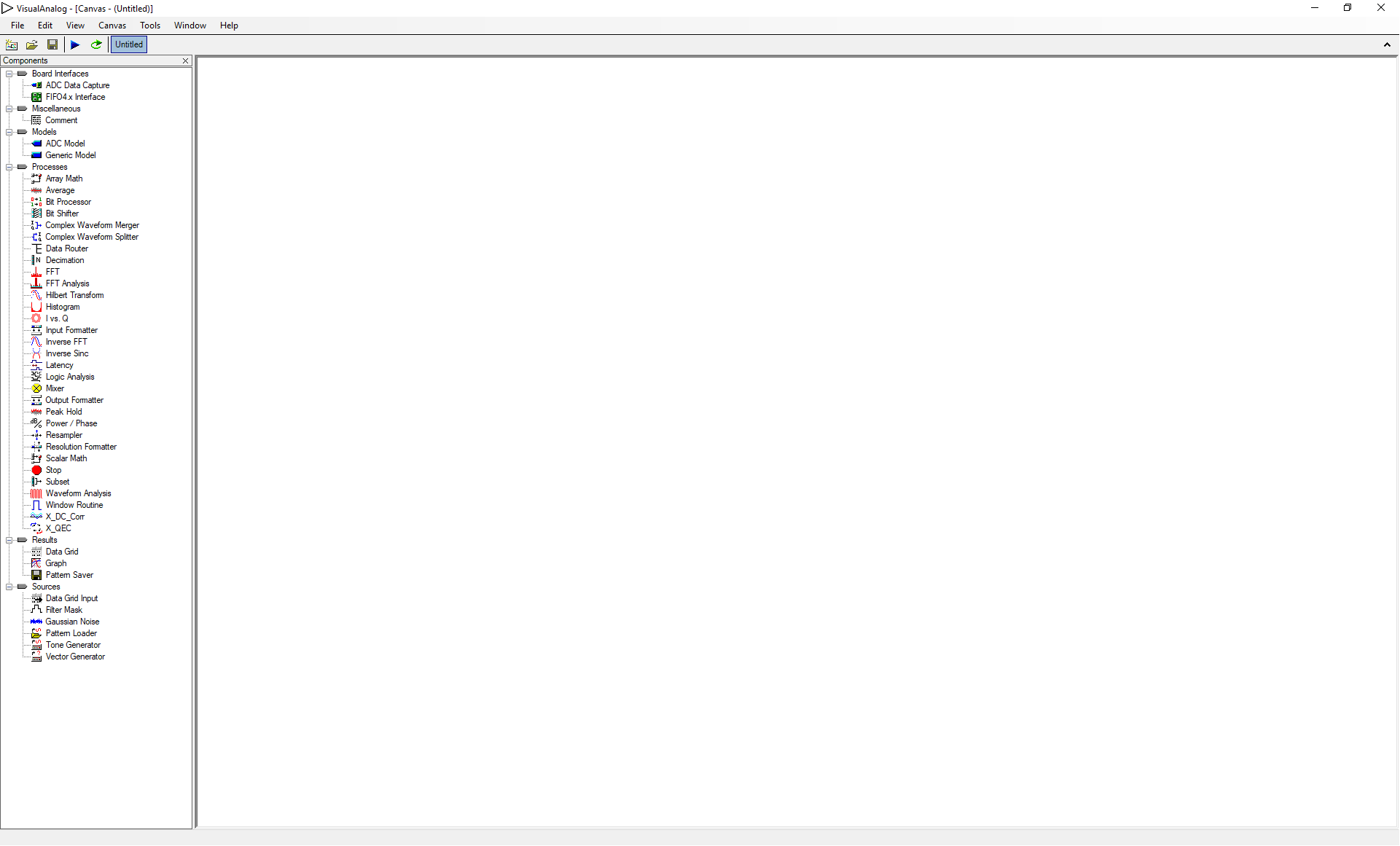
Start "Visual Analog" and open a "Blank canvas". After that, the window should look like TEI0016 Data capture Demo.
...
| anchor | Figure 11 |
|---|---|
| title | Figure 11: VisualAnalog started |
...
| Scroll Only |
|---|
|
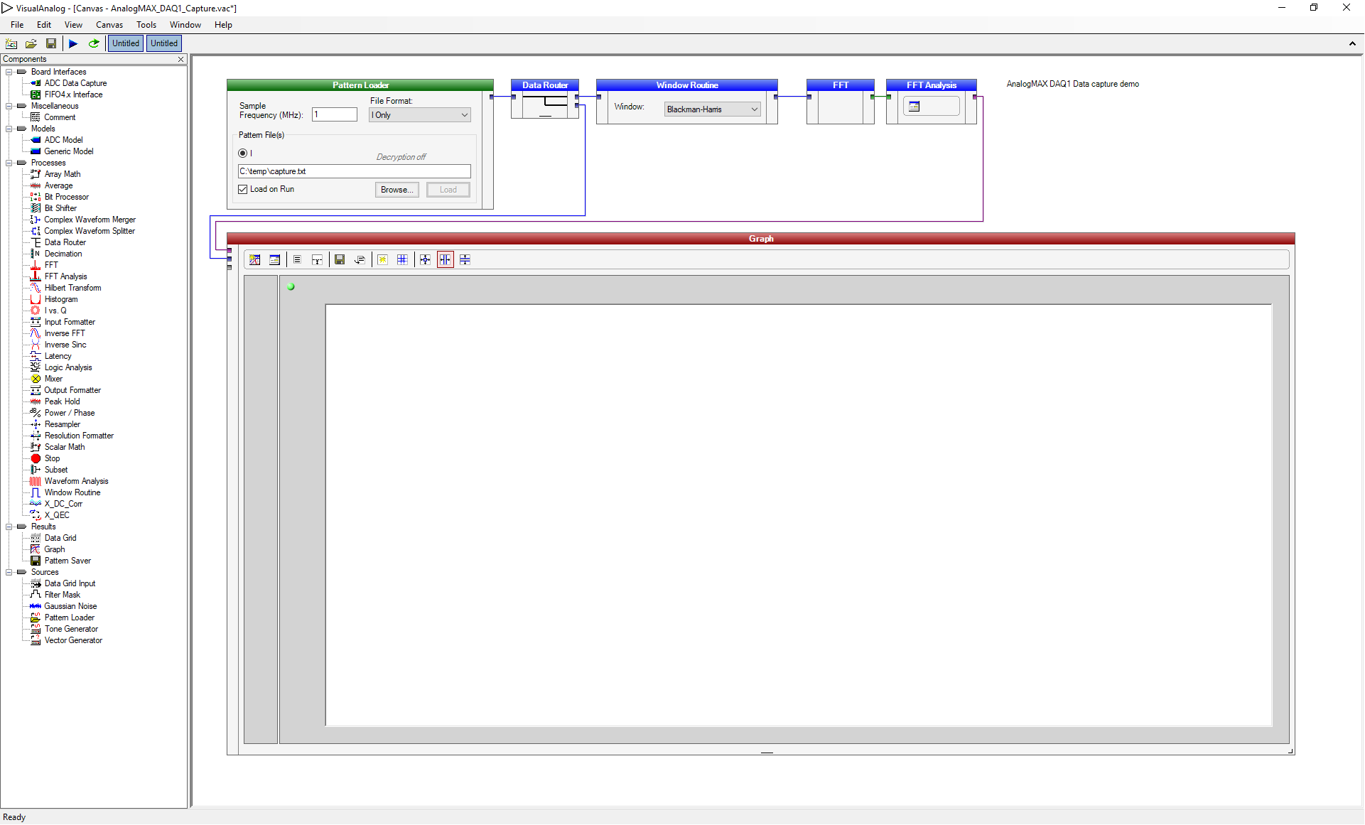
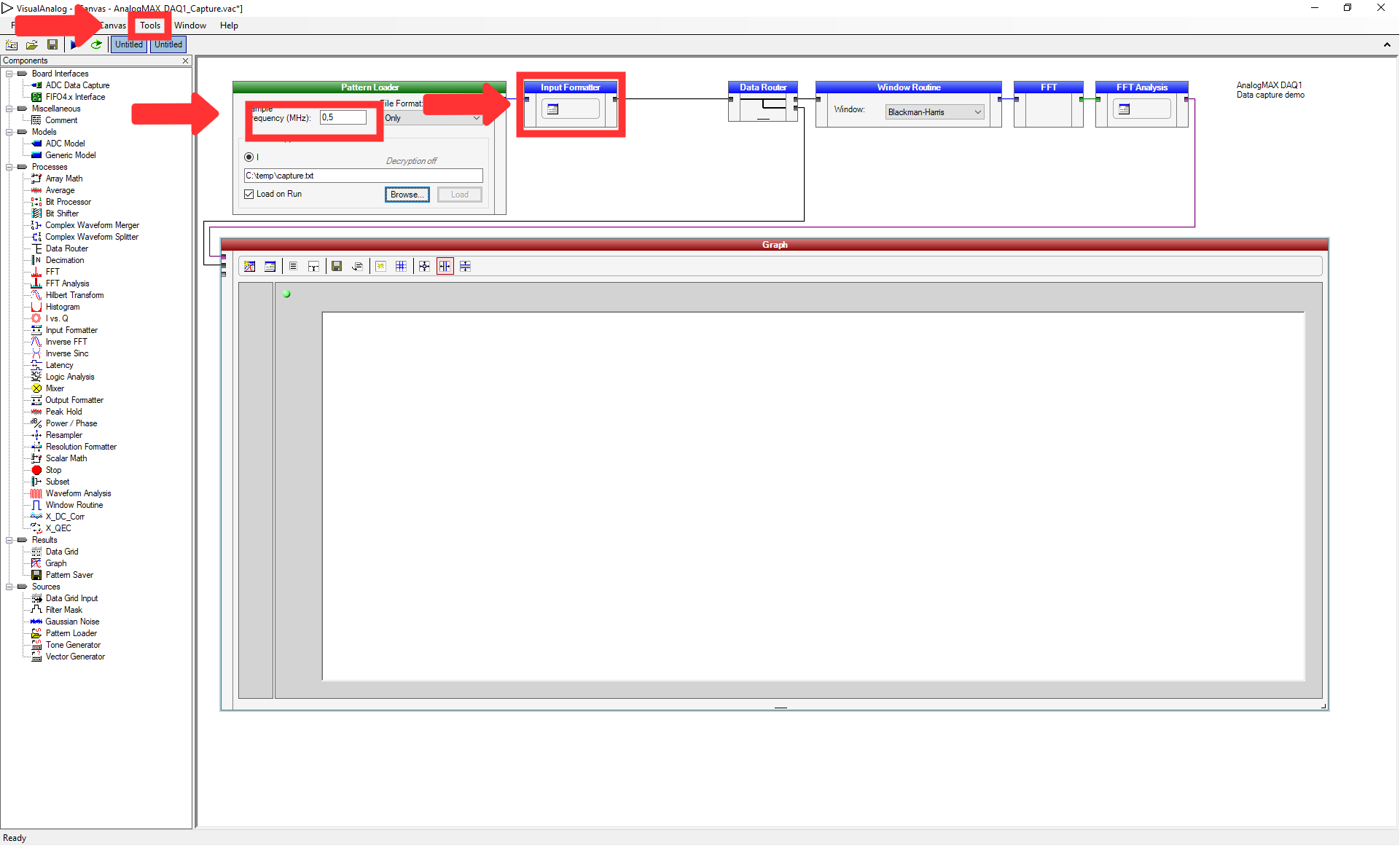
Open the file "AnalogMAX_DAQ2_Capture.vac" from the downloaded zip-file via "File → Open...". The window should look like TEI0016 Data capture Demo.
...
| anchor | Figure 12 |
|---|---|
| title | Figure 12: VisualAnalog AnalogMAX_DAQ1_Capture.vac loaded |
...
| Scroll Only |
|---|
|
...
| anchor | Figure 13 |
|---|---|
| title | Figure 13: VisualAnalog Sample Frequency changed |
...
| Scroll Only |
|---|
|
...
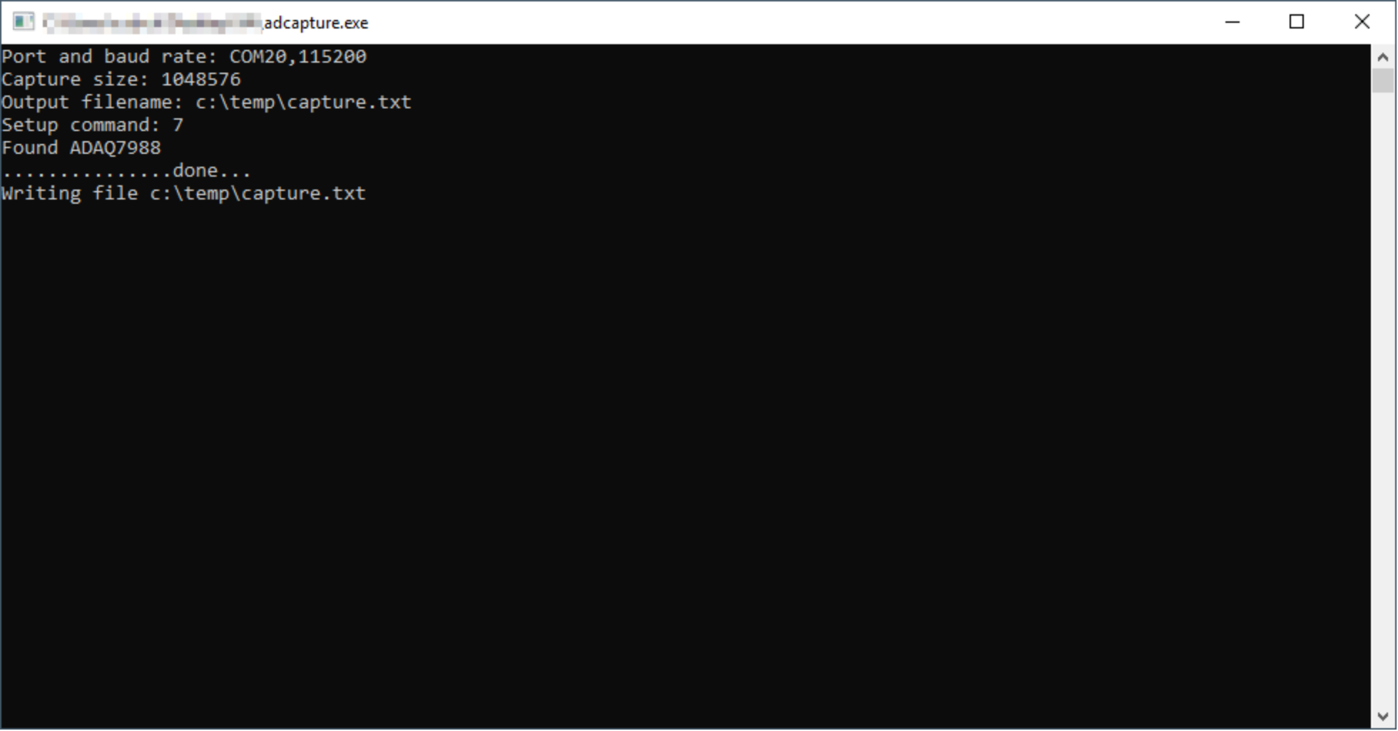
A window shows the activity of the tool "adcapture", as visible in TEI0016 Data capture Demo.
...
| anchor | Figure 14 |
|---|---|
| title | Figure 14: Adcapture.exe output |
...
| Scroll Only |
|---|
|
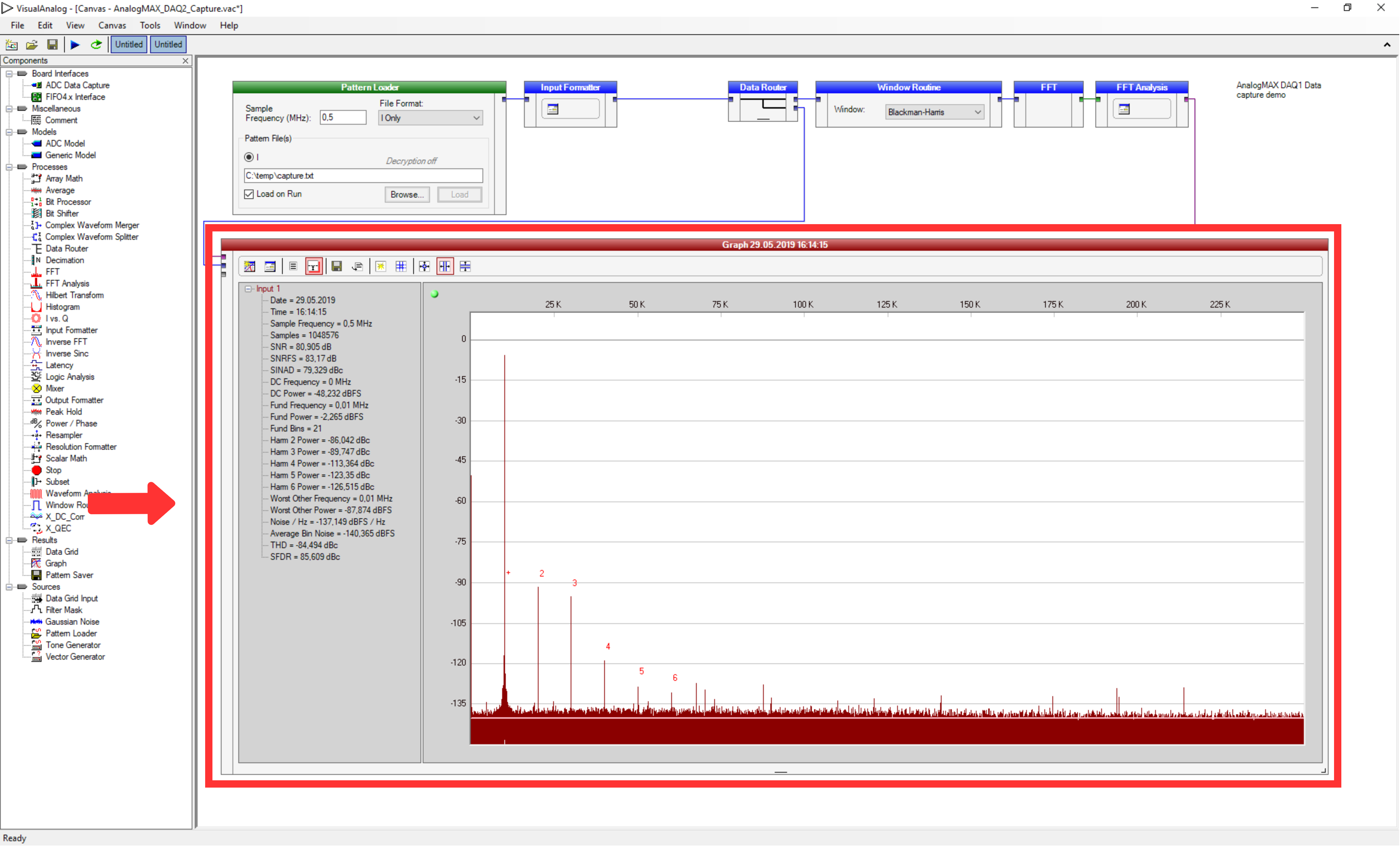
Then, using "F5" or "Canvas → Run" uses the information to create the graph in the previous window, as visible in TEI0016 Data capture Demo.
...
| anchor | Figure 15 |
|---|---|
| title | Figure 15: VisualAnalog data interpretation |
...
| Scroll Only |
|---|
|
Quick test with a terminal program
- Figure out the correct COM port number for the AnalogMAX DAQ2 board
- Open the device manager.
Open ports and identify the port used by the AnalogMAX DAQ2 as visible in TEI0016 Data capture Demo.
- Open terminal and set the parameters (example use for putty).
- Set the connection type to Serial.
- Set the "Serial line" to your above found COM port.
- Set the "Speed" to 115200.
- Use "Open" to start the connection.
- Type following character for the appropriate usage.
- "?" to get the ID (AnalogMAX DAQ2 will return "2")
- "t" to trigger ADC capture into the memory - 1M samples.
- "." to get one ADC sample.
- "+" to get 128 samples.
- "*" to get 16*1024 samples.
VisualAnalog parameter description (COM20,115200 1024 c:\temp\capture.txt 7)
...
Overview
Content Tools