Page History
...
- Intel® Cyclone 10 LP [10CL055YU484C8G],
- Package: UBGA-484
- Speed Grade: 8 (Slowest)
- Temperature: 0°C ~ 85°C
- Package compatible device 10CL016, 10CL040, 10CL080 as assembly variant on request is possible
- 16 MBit flash memory (optional up to 32 MBit possible)
- Integrated USB2.0 Programmer
- Pin Header connectors
- 256 MBit (optional up to 512 MBit possible) SDRAM
- 128 MBit (optional up to 512 MBit possible) User Quad-SPI Flash memory
- 64 MBit HyperRAM(Pseudo SRAM) (optional up to 128 MBit possible)
- FTDI - System Controller (CPLD)
- 2x MAC address EEPROM
- 2x Fast Ethernet PHY (10/100 Mbps)
- 8-channel, 12-bit, configurable ADC /DAC with on-chip reference
- D-Sub connector
- 2x RJ45 connector
- LEDs:
- Status LEDs, Power LED
- 13x User LEDs
- 7-segment display
- Push buttons:
- 2x Reset Push buttons
- 5x User Push buttons
- I/O:
- GPIO: 321
- LVDS: 132
- Power Supply:
- 5 V
- Minimum 1A
- Dimension: 95 mm x 110 mm
- Others:
- Reverse polarity of supply voltage protection
- Under/Over voltage protection
Block Diagram
| Page properties | ||||
|---|---|---|---|---|
| ||||
add drawIO object here.
|
...
| Scroll Title | ||||||||||||||||||||||||||||||||
|---|---|---|---|---|---|---|---|---|---|---|---|---|---|---|---|---|---|---|---|---|---|---|---|---|---|---|---|---|---|---|---|---|
| ||||||||||||||||||||||||||||||||
|
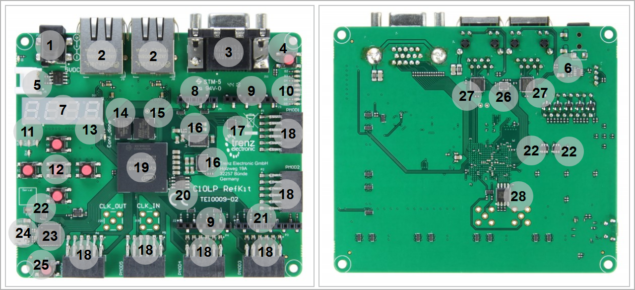
- Barrel Jack, J12
- RJ45 socket, J8...9
- D-Sub Connector, J11
- Push button(Reset), S7
- Grove connector, J5
- Under/Over Voltage Protecter, U9
- 7-segment LED, D11
- 1x6 pin header, J4
- 1x8 pin header, J2...3
- User Red LEDs, D2...9
- 8x User Red LEDs, D13...17
- 5x User Push buttons, S1- S3...6
- Red LED (CONF_DONE), D10
- PSRAM memory, U3
- SDRAM memory, U10
- Voltage Regulator, U5- U7
- AD/DA Convertor, U2
- Pmod 2x6 SMD host socket, P1...6
- Intel®Cyclone Intel®Cyclone 10 LP, U1
- Configuration memory, U5
- 1x10 pin header, J1
- EEEPROM, U15- U18- U20
- FTDI USB2 to JTAG/UART adapter, U14
- Micro USB 2.0 (receptacle) J10
- Push button (RST_GPIO), S2
- Oscillator, U22
- Ethernet PHY, U17- U19
- QSPI Flash memory, U12
Initial Delivery State
| Page properties | ||||
|---|---|---|---|---|
| ||||
Notes : Only components like EEPROM, QSPI flash and DDR3 can be initialized by default at manufacture. If there is no components which might have initial data ( possible on carrier) you must keep the table empty |
...
Overview
Content Tools