Page History
...
- Figure out the correct COM port number for the AnalogMAX DAQ1 DAQ2 board.
- Open the device manager.
Open ports and identify the port used by the AnalogMAX DAQ1 DAQ2 as visible in TEI0016 Data capture Demo.
Scroll Title anchor Figure 10 title Figure 10: Device Manager for COM port identification Scroll Ignore draw.io Diagram border true viewerToolbar true fitWindow false diagramName Device_Manager simpleViewer false width diagramWidth 882 revision 3 Scroll Only 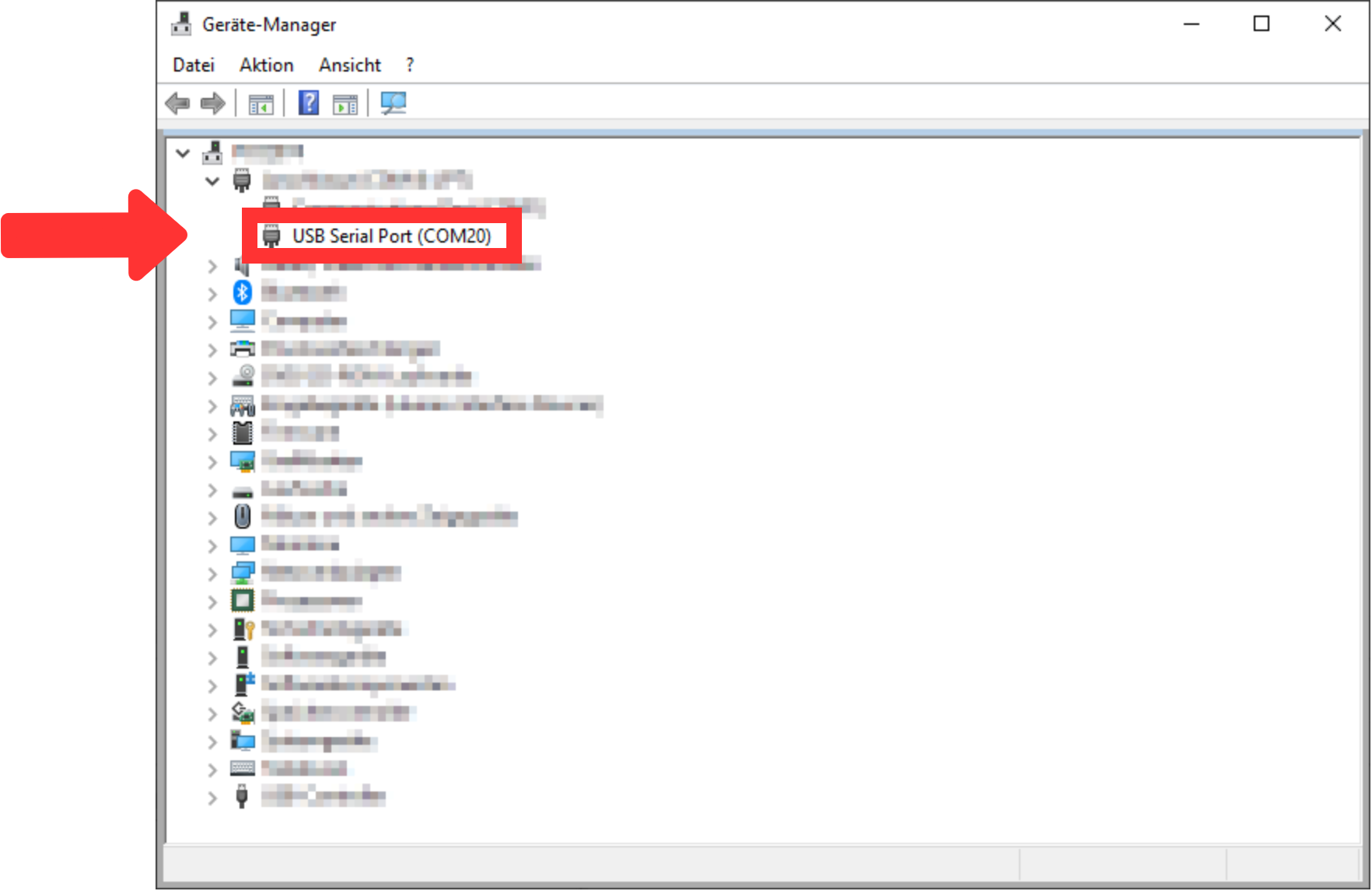
- Setup Visual Analog "External Tools..." custom menu item to launch adcapture.exe with commandline parameters.
- Download "Visual Analog" from here.
- Install "Visual Analog"
Start "Visual Analog" and open a "Blank canvas". After that, the window should look like TEI0016 Data capture Demo.
Scroll Title anchor Figure 11 title Figure 11: VisualAnalog started Scroll Ignore draw.io Diagram border true viewerToolbar true fitWindow false diagramName VisualAnalog_Started simpleViewer false width 600 diagramWidth 1921 revision 1 Scroll Only 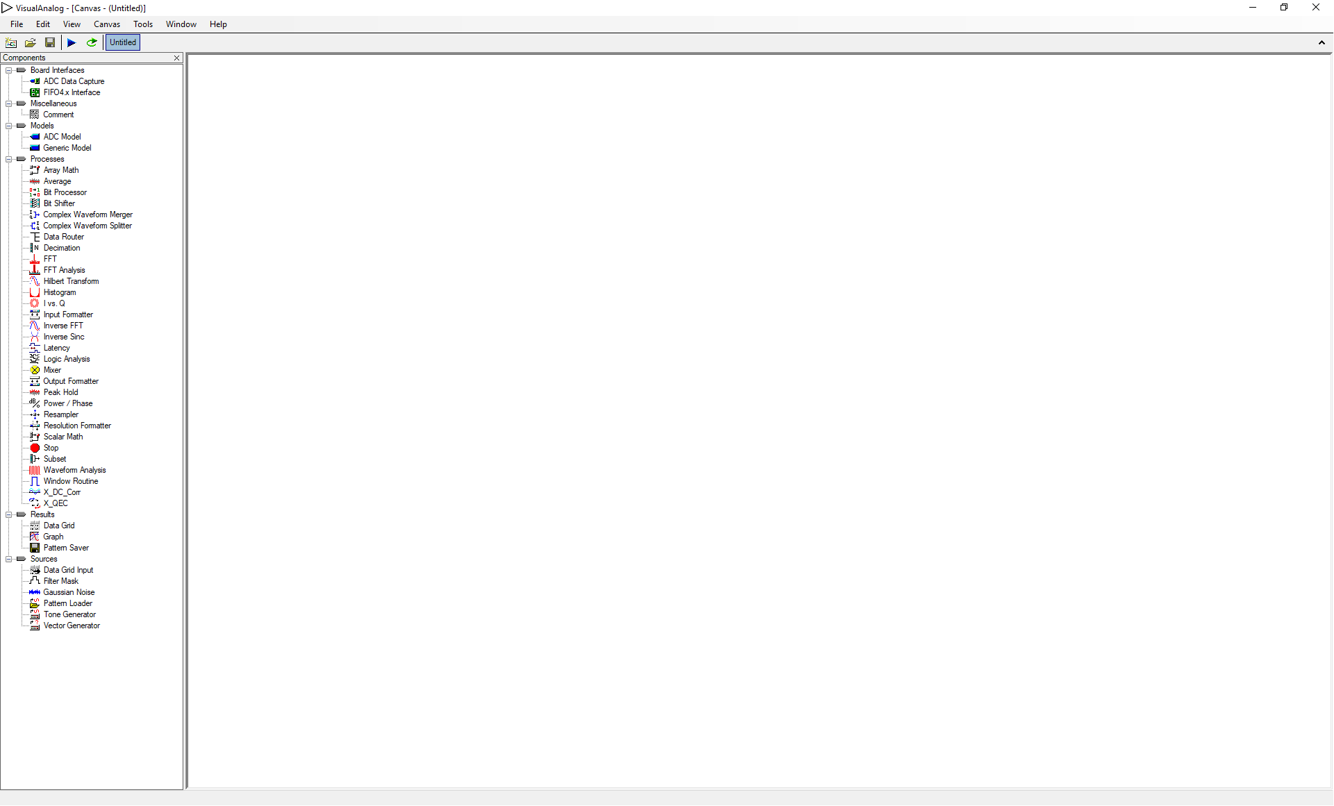
Open the file "AnalogMAX_DAQ1_Capture.vac" from the downloaded zip-file via "File → Open...". The window should look like TEI0016 Data capture Demo.
Scroll Title anchor Figure 12 title Figure 12: VisualAnalog AnalogMAX_DAQ1_Capture.vac loaded Scroll Ignore draw.io Diagram border true viewerToolbar true fitWindow false diagramName VisualAnalog_File_loaded simpleViewer false width 600 diagramWidth 1921 revision 1 Scroll Only 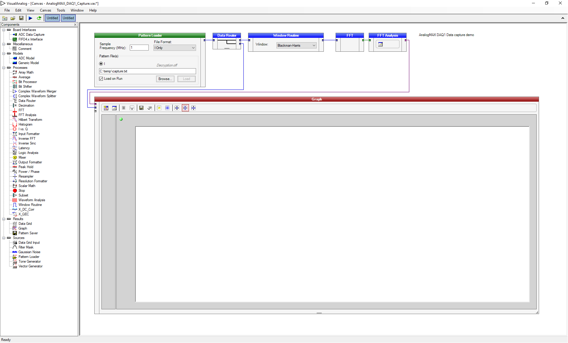
- Then change the Sample Frequency in the "Pattern Loader" to 0,5 MHz as shown in TEI0016 Data capture Demo. Attention: The "," has to be used and not the ".".
- After that, change the "Resolution" and the "Alignment" to 16 Bit by clicking on the "Input Formater".
Scroll Title anchor Figure 13 title Figure 13: VisualAnalog Sample Frequency changed Scroll Ignore draw.io Diagram border true viewerToolbar true fitWindow false diagramName VisualAnalog_Frequency_Changed simpleViewer false width 600 diagramWidth 1921 revision 5 Scroll Only 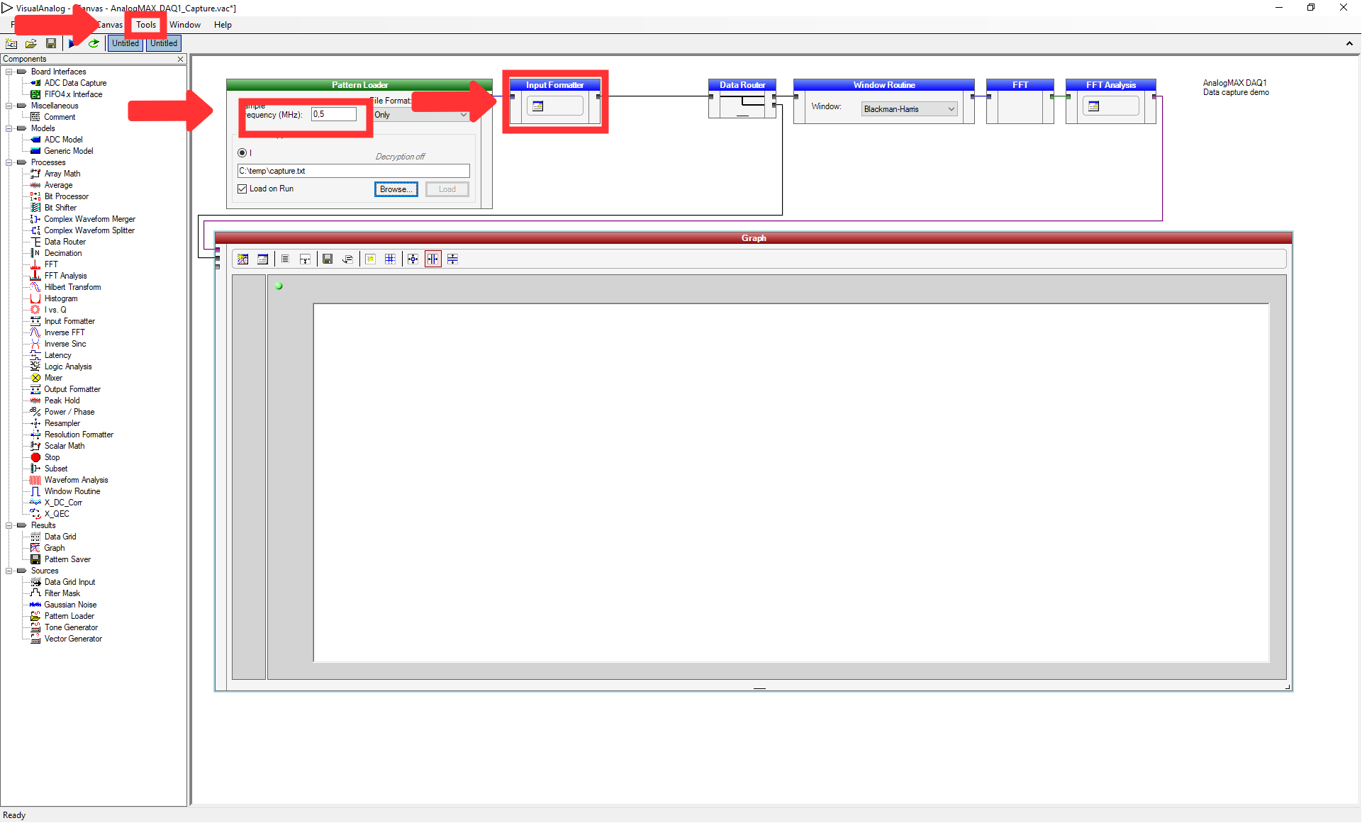
- Press "Tools → External Tools..." to prepare the usage of the adcapture.exe.
- Click "Add" in the opened window and insert the name "adcapture" in the "Display Text". Select the file "adcapture.exe" from the downloaded zip-file after using the button "Browse..." for the "File Name", and insert "COM20,115200 1024 c:\temp\capture.txt 7" for the "Arguments". The parameters are the COM port (COM port 20 in our case), the baud rate, the number of samples, the location to store the data and a value to adjust the system. Then, click on "Ok".
- Launch adcapture.exe and after completion click run to update the screen.
- Select the above inserted tool by selecting "Tools → adcapture".
A window shows the activity of the tool "adcapture", as visible in TEI0016 Data capture Demo.
Scroll Title anchor Figure 14 title Figure 14: Adcapture.exe output Scroll Ignore draw.io Diagram border true viewerToolbar true fitWindow false diagramName adcapture_exe simpleViewer false width diagramWidth 980 revision 1 Scroll Only 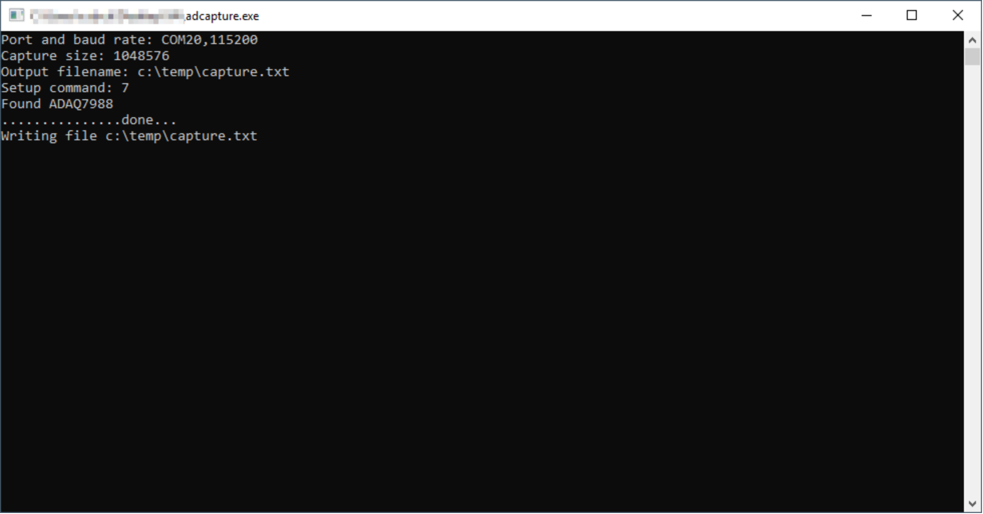
Then, using "F5" or "Canvas → Run" uses the information to create the graph in the previous window, as visible in TEI0016 Data capture Demo.
Scroll Title anchor Figure 15 title Figure 15: VisualAnalog data interpretation Scroll Ignore draw.io Diagram border true viewerToolbar true fitWindow false diagramName VisualAnalog_Results simpleViewer false width 600 diagramWidth 1921 revision 5 Scroll Only 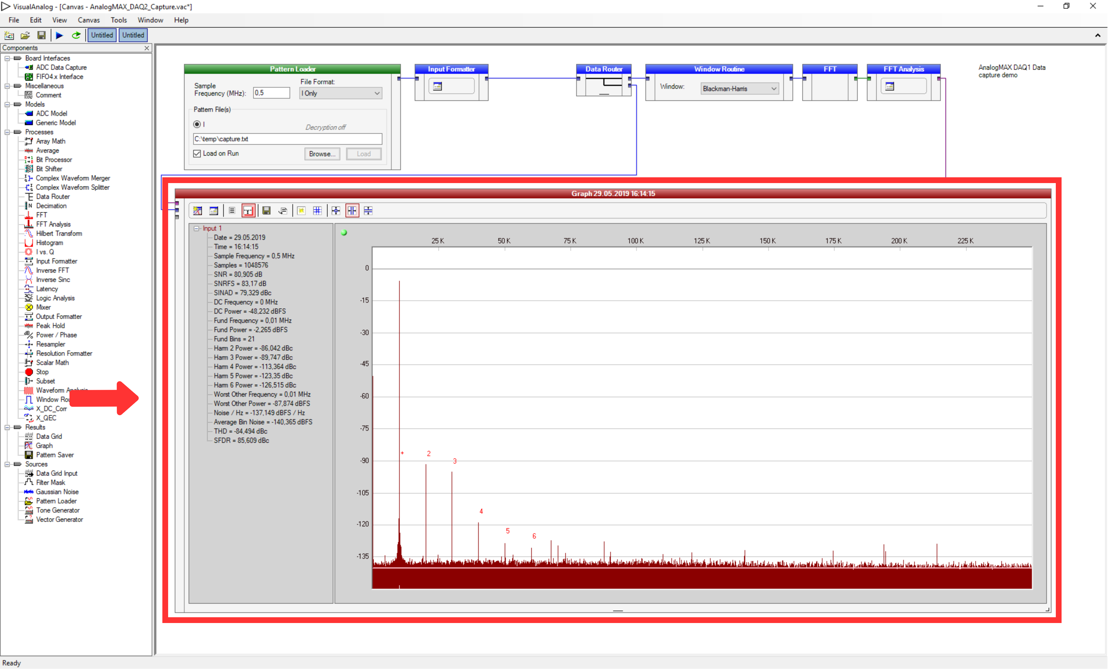
...
Overview
Content Tools