...
| Scroll Title |
|---|
| anchor | Figure_1 |
|---|
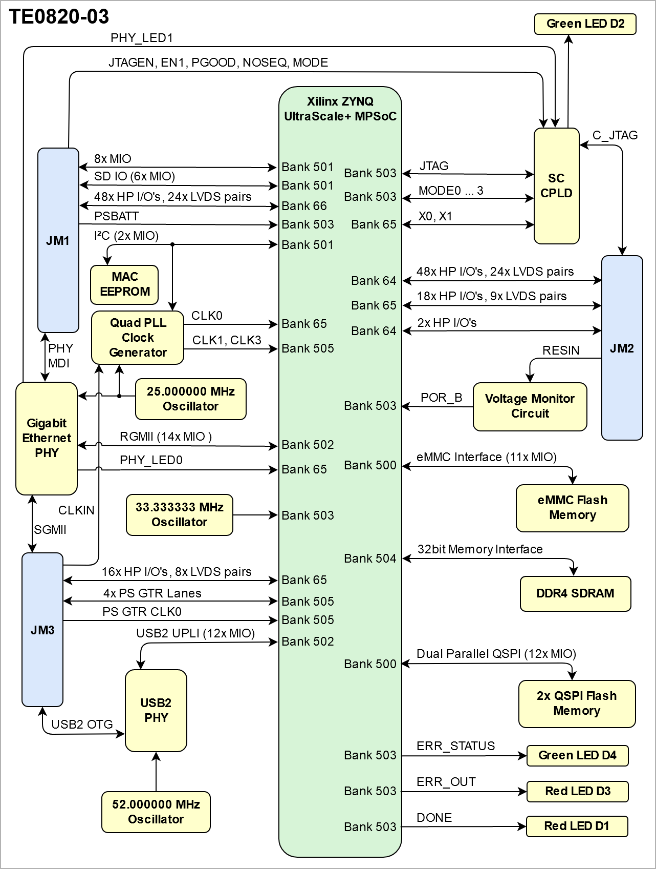
| title | Figure 1: TE0820-03 block diagram |
|---|
|
| Scroll Ignore |
|---|
| draw.io Diagram |
|---|
| border | false |
|---|
| viewerToolbar | true |
|---|
| fitWindow | false | diagramDisplayName |
|---|
| lbox | true |
|---|
| revision | 2 |
|---|
| diagramName | TE0820 block diagram |
|---|
| simpleViewer | false |
|---|
| width | links | auto |
|---|
| tbstyle | hidden |
|---|
| lbox | true |
|---|
| diagramWidth | 641 |
|---|
| revision | 1 |
|---|
|
|
| Scroll Only |
|---|
|
|
Main Components
| Scroll Title |
|---|
| anchor | Figure_2 |
|---|
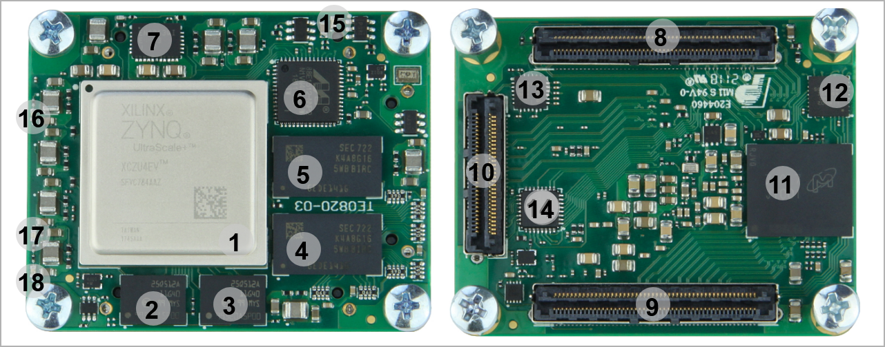
| title | Figure 2: TE0820-03 main components |
|---|
|
| Scroll Ignore |
|---|
| draw.io Diagram |
|---|
| border | false |
|---|
| viewerToolbar | true |
|---|
| fitWindow | false | diagramDisplayName |
|---|
| lbox | true |
|---|
| revision | 3 |
|---|
| diagramName | TE0820 main components |
|---|
| simpleViewer | false |
|---|
| width | links | auto |
|---|
| tbstyle | hidden |
|---|
| lbox | true |
|---|
| diagramWidth | 641 |
|---|
| revision | 3 |
|---|
|
|
| Scroll Only |
|---|
|
|
- Xilinx Zynq UltraScale+ MPSoC, U1
- 1.8V, 512 Mbit QSPI flash memory, U7
- 1.8V, 512 Mbit QSPI flash memory, U17
- 8 Gbit (512 x 16) DDR4 SDRAM, U2
- 8 Gbit (512 x 16) DDR4 SDRAM, U3
- Marvell Alaska 88E1512 integrated 10/100/1000 Mbps energy efficient ethernet transceiver, U8
- 6A PowerSoC DC-DC converter (PL_VCCINT, 0.85V), U5
- B2B connector Samtec Razor Beam™ LSHM-150, JM1
- B2B connector Samtec Razor Beam™ LSHM-150, JM2
- B2B connector Samtec Razor Beam™ LSHM-130, JM3
- 8 GByte eMMC memory, U6
- Lattice Semiconductor MachXO2 System Controller CPLD, U21
- I2C programmable, any frequency , any output quad clock generator, U10
- Highly integrated full featured hi-speed USB 2.0 ULPItransceiver, U18
- LED D1(Red) Done Pin
- LED D2 (Green) CPLD Status, User LED
- LED D3 (Red) PS Error
- LED D4 (Green) PS Error Status
...
| Scroll Title |
|---|
| anchor | Figure_3 |
|---|
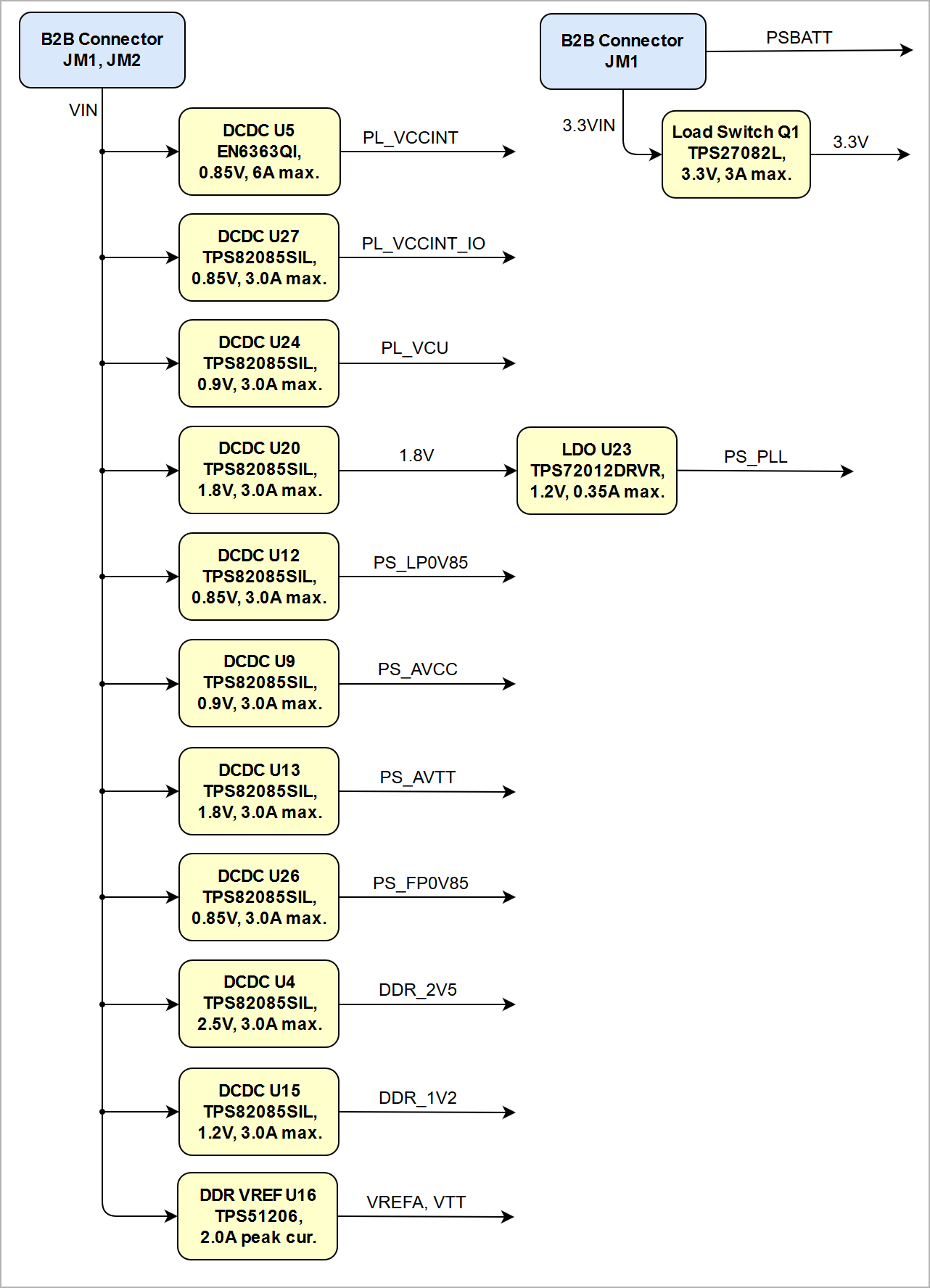
| title | Figure 3: TE0820-03 Power Distribution Diagram |
|---|
|
| Scroll Ignore |
|---|
| draw.io Diagram |
|---|
| border | false |
|---|
| viewerToolbar | true |
|---|
| fitWindow | false | diagramDisplayName |
|---|
| lbox | true |
|---|
| revision | 1 |
|---|
| diagramName | TE0820 power distribution diagram |
|---|
| simpleViewer | false | width |
|---|
| links | auto |
|---|
| tbstyle | hidden |
|---|
| lbox | true |
|---|
| diagramWidth | 641 |
|---|
| revision | 1 |
|---|
|
|
| Scroll Only |
|---|
|
|
See also Xilinx datasheet DS925 for additional information. User should also check related base board documentation when intending base board design for TE0820 module.
...
| Scroll Title |
|---|
| anchor | Figure_4 |
|---|
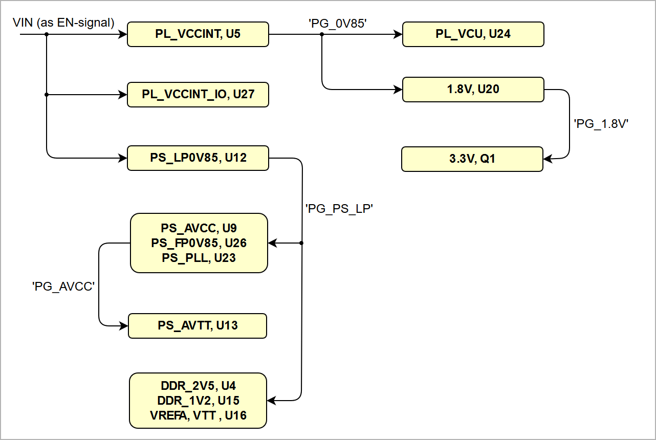
| title | Figure 4: TE0820-03 Power-on Sequence Diagram |
|---|
|
| Scroll Ignore |
|---|
| draw.io Diagram |
|---|
| border | false |
|---|
| viewerToolbar | true |
|---|
| fitWindow | false | diagramDisplayName | lbox | true |
|---|
| revision | 1 |
|---|
| diagramName | TE0820 Power-on Sequence |
|---|
| simpleViewer | false | width |
|---|
| links | auto |
|---|
| tbstyle | hidden |
|---|
| lbox | true |
|---|
| diagramWidth | 641 |
|---|
| revision | 1 |
|---|
|
|
| Scroll Only |
|---|
|
|
For highest efficiency of the on-board DC-DC regulators, it is recommended to use one 3.3V power source for both VIN and 3.3VIN power rails. Although VIN and 3.3VIN can be powered up in any order, it is recommended to power them up simultaneously.
...
Date | Revision | Contributors | Description |
|---|
| Page info |
|---|
| modified-date |
|---|
| modified-date |
|---|
| dateFormat | yyyy-MM-dd |
|---|
|
| | Page info |
|---|
| infoType | Current version |
|---|
| dateFormat | yyyy-MM-dd |
|---|
| type | Flat |
|---|
|
| | Page info |
|---|
| infoType | Modified by |
|---|
| dateFormat | yyyy-MM-dd |
|---|
| type | Flat |
|---|
|
| - Number of MIOs on JM1 corrected (6+6+2)
| 2019-11-28 | v.81 | Martin Rohrmüller | - typo and designator in section USB interface corrected
|
| 2019-10-30 | v.80 | John Hartfiel | |
| 2019-09-17 | v79 | Martin Rohrmüller | - Updated according to PCN-20190110: eMMC, QSPI-Flash
|
| v.78 | Martin Rohrmüller | - Corrected PJTAG Mio Pin29 in table 8
|
2019-05-08 | v.77 | John Hartfiel | - Corrected EEPROM I2C Address
- Correction USB PHY connection
|
| v.74 | John Hartfiel | |
| v.73 | John Hartfiel | - typo correction
- update CPLD section
- add LEDs to component list
- add 3D picture of REV03 instead of REV01 picture
|
| v.69 | Ali Naseri | |
| v.61 | John Hartfiel | - Rework chapter currently available products
- add PJTAG note to MIOtable
|
| 2018-03-12 | v.54 |
| - Correction Power Rail Section
|
| 2017-11-20 | v.51 | John Hartfiel | - Correction Default MIO Configuration Table
|
| 2017-11-10 | v.50 | John Hartfiel | - Replace B2B connector section
|
| 2017-10-18 | v.49 | John Hartfiel | |
| 2017-09-25 | v.48 | John Hartfiel | - Correction in the "Board to Board (B2B) I/Os" section
- Update in the "Variants Currently In Production" section
|
| 2017-09-18 | v.47 | John Hartfiel | |
| 2017-08-30 | v.46 | Jan Kumann | |
| | John Hartfiel | - Correction in the "Key Features" section.
|
| 2017-08-21 | v.34 | John Hartfiel | - "Initial delivery state" section updated.
|
| 2017-08-21 | v.33 | Jan Kumann | - HW revision 02 block diagram added.
- Power distribution and power-on sequence diagram added.
- System Controller CPLD and DDR4 SDRAM sections added.
- TRM update to the template revision 1.6
- Weight section removed.
- Few minor corrections.
|
| | John Hartfiel | - Style changes
- Updated "Boot Mode", "HW Revision History", "Variants Currently In Production" sections
- Correction of MIO SD Pin-out, System Controller chapter
- Update and new sub-sections on "On Board Peripherals and Interfaces" sections
|
2017-08-07 | v.5 | Jan Kumann | |
| -- | all | | Page info |
|---|
| infoType | Modified users |
|---|
| type | Flat |
|---|
| showVersions | false |
|---|
|
| |
...