...
| Scroll Title |
|---|
| anchor | Figure_OV_BD |
|---|
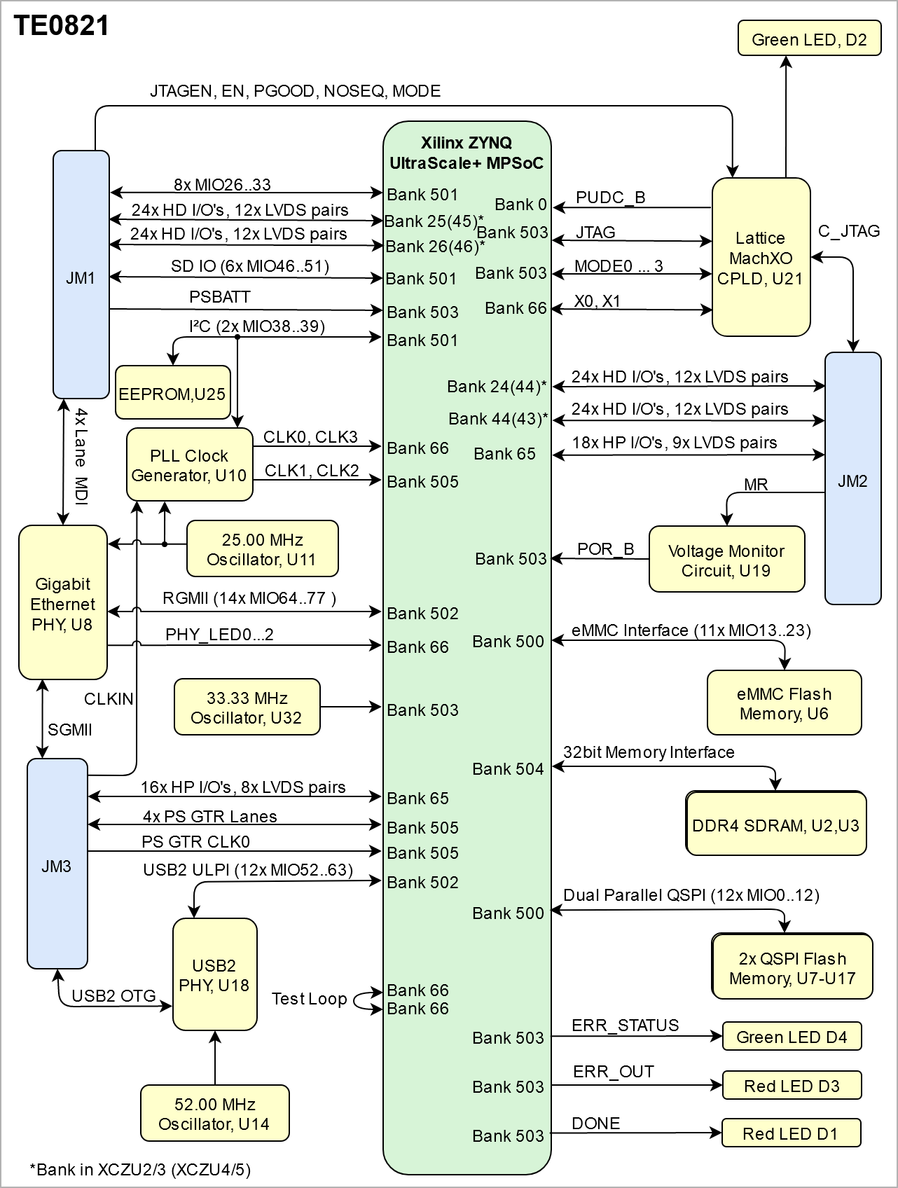
| title | TE0821 block diagram |
|---|
|
| Scroll Ignore |
|---|
| draw.io Diagram |
|---|
| border | false |
|---|
| |
|---|
| diagramName | TE0821_OV_BD |
|---|
| simpleViewer | false |
|---|
| width | |
|---|
| links | auto |
|---|
| tbstyle | hidden |
|---|
| diagramDisplayName | |
|---|
| lbox | true |
|---|
| diagramWidth | 641 |
|---|
| revision | 14 |
|---|
|
|
| Scroll Only |
|---|
|
|
Main Components
...
| Scroll Title |
|---|
| anchor | Table_OV_IDS |
|---|
| title | Initial delivery state of programmable devices on the module |
|---|
|
| Scroll Table Layout |
|---|
| orientation | portrait |
|---|
| sortDirection | ASC |
|---|
| repeatTableHeaders | default |
|---|
| style | |
|---|
| widths | |
|---|
| sortByColumn | 1 |
|---|
| sortEnabled | false |
|---|
| cellHighlighting | true |
|---|
|
Storage device name | Content | Notes |
|---|
SPI Flash OTP Area | Not programmed | Except serial number programmed by flash vendor. | SPI Flash Quad Enable bit | Programmed | - | SPI Flash main array | Not | ProgrammedeMMC | Not Programmed | DDR4 Memory | programmed | - | eFUSE USER | Not programmed | - | eFUSE Security | Not programmed | - | | Si5338 OTP NVM | Not programmed | - | | CPLD (LCMXO2-256HC) | SC0820-02 QSPI Firmware | See Boot Process section.Not Programmed |
|
Configuration Signals
| Page properties |
|---|
|
- Overview of Boot Mode, Reset, Enables.
|
Two different firmware versions are available, one with the QSPI boot option and other with the SD Card boot option.
| Scroll Title |
|---|
| anchor | Table_OV_BP |
|---|
| title | Boot process. |
|---|
|
| Scroll Table Layout |
|---|
| orientation | portrait |
|---|
| sortDirection | ASC |
|---|
| repeatTableHeaders | default |
|---|
| style | |
|---|
| widths | |
|---|
| sortByColumn | 1 |
|---|
| sortEnabled | false |
|---|
| cellHighlighting | true |
|---|
|
MODE Signal StatePin | Boot Mode |
|---|
| Low | QSPI | | High | SD Card |
|
| Scroll Title |
|---|
| anchor | Table_OV_RST |
|---|
| title | Reset process. |
|---|
|
| Scroll Table Layout |
|---|
| orientation | portrait |
|---|
| sortDirection | ASC |
|---|
| repeatTableHeaders | default |
|---|
| style | |
|---|
| widths | |
|---|
| sortByColumn | 1 |
|---|
| sortEnabled | false |
|---|
| cellHighlighting | true |
|---|
|
|
...
| Scroll Title |
|---|
| anchor | Table_SIP_B2B |
|---|
| title | General PL I/O to B2B connectors information |
|---|
|
| Scroll Table Layout |
|---|
| orientation | portrait |
|---|
| sortDirection | ASC |
|---|
| repeatTableHeaders | default |
|---|
| style | |
|---|
| widths | |
|---|
| sortByColumn | 1 |
|---|
| sortEnabled | false |
|---|
| cellHighlighting | true |
|---|
|
| FPGA Bank | B2B Connector | I/O Signal Count | I/O Signal Count | Voltage Level | Notes |
|---|
|
...
64 | HP | JM2 | 48 | User | Max voltage 1.8V | 64 | HP | JM2 | 2 | User | Max voltage 1.8V | | 65 | HP | JM2 | 18 | User | Max voltage 1.8V | 65 | HP | JM3 | 16 | User | Max voltage 1.8V | 66 | HP | JM1 | 48 | User | Max voltage 1.8V | | 500 | MIO | JM1 | 8 | 1.8V | - | 501 | MIO | JM1 | 6 | 3.3V | - | 505 | GTR | JM3 | 4 lanes | - | - | 505 | GTR CLK | JM3 | 1 differential input | - | - |
|
JTAG Interface
JTAG access to the TExxxx SoM through B2B connector JMX.
| Scroll Title |
|---|
| anchor | Table_SIP_JTG |
|---|
| title | JTAG pins connection |
|---|
|
JTAG access to the TExxxx SoM through B2B connector JMX.
| Scroll Title |
|---|
| anchor | Table_SIP_JTG |
|---|
| title | JTAG pins connection |
|---|
|
| Scroll Table Layout |
|---|
| orientation | portrait |
|---|
| sortDirection | ASC |
|---|
| repeatTableHeaders | default |
|---|
| style | |
|---|
| widths | |
|---|
| sortByColumn | 1 |
|---|
| sortEnabled | false |
|---|
| cellHighlighting | true |
|---|
|
JTAG Signal | B2B Connector |
|---|
| TMS | JM2-93 | | TDI | JM2-95 | | TDO | JM2-97 | | TCKJTAG_EN | JM2-99 |
|
Pin 89 JTAGEN of B2B connector JM1 is used to control which device is accessible via JTAG. If set to low or grounded, JTAG interface will be routed to the Xilinx Zynq MPSoC. If pulled high, JTAG interface will be routed to the System Controller CPLD.
MIO Pins
| Page properties |
|---|
|
you must fill the table below with group of MIOs which are connected to a specific components or peripherals, you do not have to specify pins in B2B, Just mention which B2B is connected to MIOs. The rest is clear in the Schematic. Example: | MIO Pin | Connected to | B2B | Notes |
|---|
| MIO12...14 | SPI_CS , SPI_DQ0... SPI_DQ3 SPI_SCK | J2 | QSPI |
|
...
| Scroll Title |
|---|
| anchor | Figure_PWR_PD |
|---|
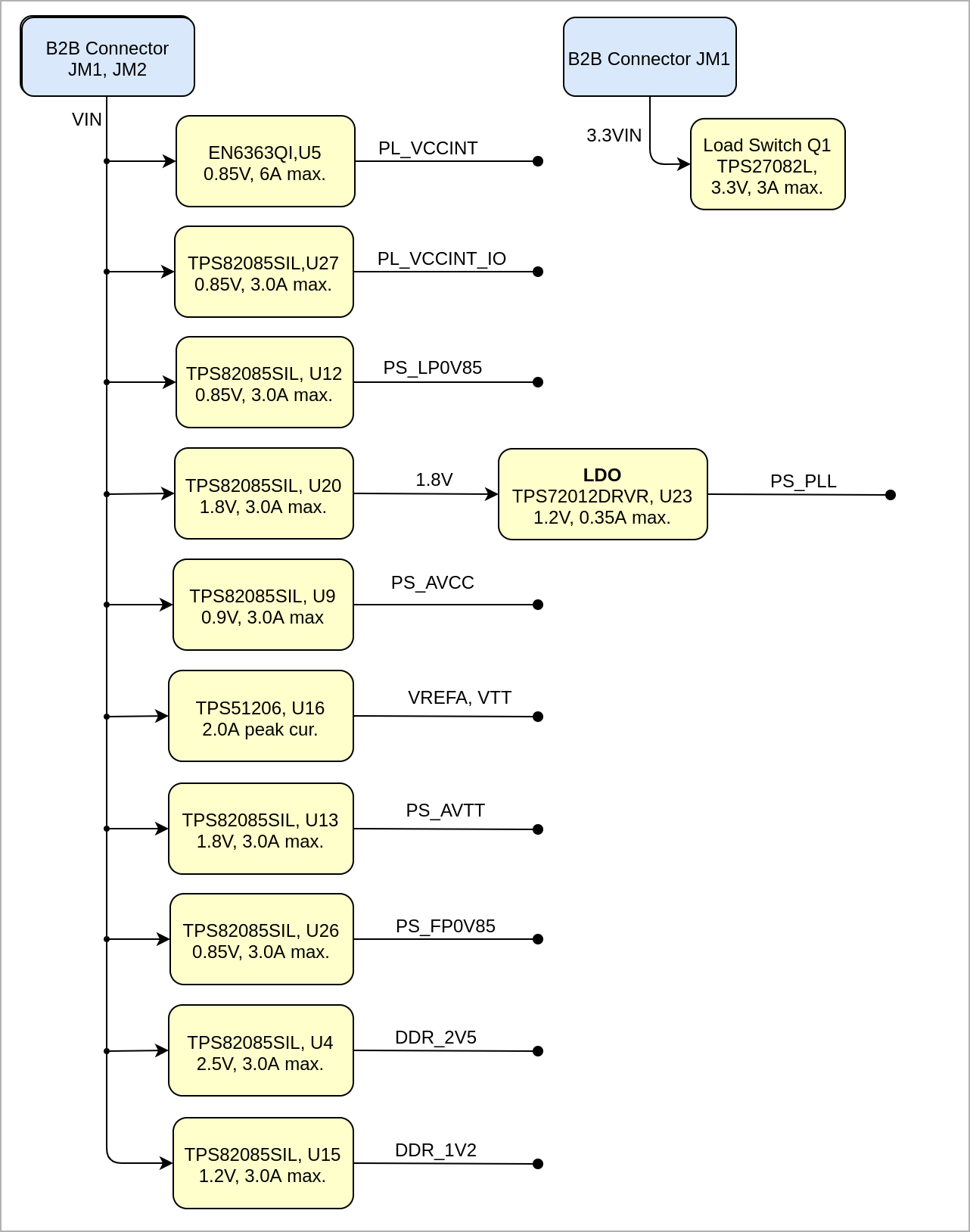
| title | Power Distribution |
|---|
|
| Scroll Ignore |
|---|
| draw.io Diagram |
|---|
| border | false |
|---|
| |
|---|
| diagramName | TE0821_PWR_PD |
|---|
| simpleViewer | false |
|---|
| width | |
|---|
| links | auto |
|---|
| tbstyle | hidden |
|---|
| diagramDisplayName | |
|---|
| lbox | true |
|---|
| diagramWidth | 641 |
|---|
| revision | 12 |
|---|
|
|
| Scroll Only |
|---|
|
|
Power-On Sequence
...
| Page properties |
|---|
|
- This section is optional and only for modules.
use "include page" macro and link to the general B2B connector page of the module series, For example: 6 x 6 SoM LSHM B2B Connectors
| Include Page |
|---|
PD: 6 x 6 SoM LSHM B2B Connectors PD:6 x 6 SoM LSHM B2B Connectors |
|
? x ? modules use two or three Samtec Micro Tiger Eye Connector on the bottom side.
3 x REF-??????? (compatible to ????????), (?? pins, ?? per row)
B2B Connectors
| Include Page |
|---|
| PD:6 x 6 SoM LSHM B2B Connectors |
|---|
| PD:6 x 6 SoM LSHM B2B Connectors |
|---|
|
|
| Include Page |
|---|
| PD:4 x 5 SoM LSHM B2B Connectors |
|---|
| PD:4 x 5 SoM LSHM B2B Connectors |
|---|
|
...
Technical Specifications
Absolute Maximum Ratings
...
Physical Dimensions
PCB thickness: 1.74 mm.
...