LabX Demo
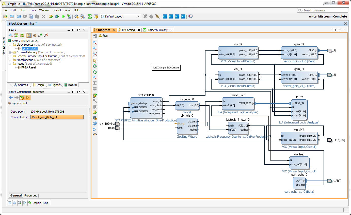
This design converts TE0725 into mini lab instrument:
- I/O Monitor and excerciser (all 84 I/O in B2B connectors)
- 84 Channel Logic Analyzer, 4K deep (on A15T, an be larger with larger FPGA)
- UART Echo with 1 Channel Logic Analyzer, 128K deep
- 2 Channel Frequency Counter (each channel can use any pin from one connector)
- 2 Channel Duty Cycle Instrument (each channel can use any pin from one connector)
| ILA Core Name | Sample Rate | Depth | Connection |
|---|---|---|---|
| xmod_uart | 10MHz | 128K | UART RXD in XMOD connector |
| POF | 375MHz | 128K | LVDS input from POF fibre receiver |
| J1_J2 | 100MHz | 4K | J1: 42 pins, J2: 42 pins |
| Channel Name | Measurement Type | Connection |
|---|---|---|
| CFCLK | Frequency | Free running configuration clock, nominal 66MHz |
| J1_FREQ | Frequency | input multiplexer, from any pin in J1 |
| J1_DUTY | Duty Cycle | input multiplexer, from any pin in J1 |
| J2_FREQ | Frequency | input multiplexer, from any pin in J2 |
| J2_DUTY | Duty Cycle | input multiplexer, from any pin in J2 |
| POF_FREQ | Frequency | LVDS input from POF receiver |
| POF_DUTY | Duty Cycle | LVDS input from POF receiver |
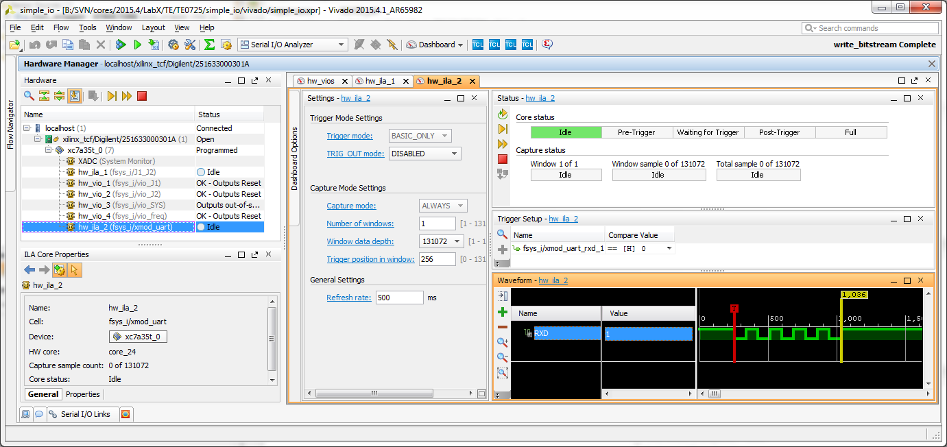
Example screenshot, Uppercase "U" was sent from UART at 115200 baud, trigger on RXD 0 logic analyzer trace captured.
Overview
Content Tools