FPGA's and SoC can be used for many more advanced functions as making a LED to blink. However "LED Blinky" is considered a "Hello World" for systems that can not otherwise say Hello.
Requirements
To make LED to Blink (under user control) following requirements are needed:
- Some Programmable Device: MCU, CPU, CPLD, FPGA, SoC
- Working Programming or Configuration interface or means to boot the Programmable Device
- Timing Source (Clock), can be external or internal, must be be enabled
- Active Power to all required power domains of the Programmable Device
- Release of main Reset
- LED Connected to some user controllable I/O Port of the Programmable Device
- LED must be assembled with right polarity and proper current limiting resistor
- Valid I/O Voltage applied to the I/O Bank with the user LED
If any of those requirements are missing, you will most likely fail with the simple task to get an LED to Blink.
Programmable Device
Timing Source
Valid I/O Voltage
It is very common that modern Integrated Circuits have separate power supply pins for I/O Voltage. That voltage if applied control the output levels from the device, if the Voltage is too low or missing then it is not possible to have enough current from the device I/O Pin to make a LED Lit.
FPGA and SoC SoM's can have fixed and user controlled Voltages for the I/O Banks. It is important to assure that the I/O Bank that controls the LED has a valid Supply Voltage applied.
If you are not sure about the I/O Banks Voltage supplies then there are some options to try.
DONE LED
If there is on board LED directly connected to FPGA "DONE" output, then it is also possible to control it as long as it is possible to configure the FPGA (or PL portion of Zynq). For Zynq the PS subsystem is not needed if configuration is done via JTAG.
The good thing about Done LED is that if it is available it has fixed location, there is no need to assign it to some pin and it has fixed available power as well. The tricky parts is that DONE output is controlled by FPGA Primitive so the code to control the Done LED is different from that of normal PL I/O Controlled LED.
MIO LED
If there is a LED directly connected to lower MIO Bank of the Zynq then this LED is also always controllable, as this Bank has to be powered for the device to boot. This LED can also be controlled if the PL portion of the Zynq is not configured or even un-powered.
VIO LED
This is an option that is always available as long as we have JTAG Connection to the PL.
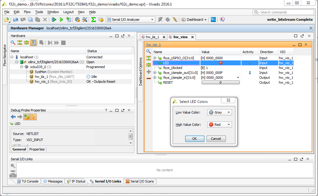
Example of VIO LED, the SoM being used is Kintex UltraScale TE0841, the LED is implemented in F32C Softcore Bootloader that is waiting for Arduino IDE to download a sketch. There is no limit for the number of virtual LED's. It is also possible to attach those VIO LED's to Zynq GPIO when using EMIO mulitplexing, so the same GUI would show LED's controlled by Zynq PS during boot or running Linux.
LED's on TE SoM's and Baseboards
| MIO LED | DONE LED | User LED PL | Notes | |
|---|---|---|---|---|
| TE0710 | - | |||
| TE0711 | - | |||
| TE0712 | - | No* | Yes* | LED's are routed to PL I/O by System Control CPLD |
| TE0714 | - | No | Yes | One fixed LED on PL,1.8V or 3.3V I/O Voltage always present |
| TE0720 | MIO7 | Yes, Fixed | Yes* | System control CPLD can remap the LED functions during FSBL |
| TE0725 | - | Yes | Yes | LED's power always available |
| TE0741 | - | |||
| TE0745 | MIO | - | ||
| TE0782 | ||||
| TE0841 | - | - | Yes |
| Base | User LED's | Notes |
|---|---|---|
| TE0701 | up to 8 max | All LED's controlled by the System Control CPLD, some require user I/O Bank voltage |
| TE0703 | 2* | User supplied I/O Voltage |
| TE0705 | ||
| TE0706 | 0 | Can use RJ45 LED's as PL User LED's |
Blinky Examples
Arduino F32C
F32C is an Open Source Soft Processor and SoC system that has ready to use support for Arduino IDE (using Arduino IDE package manager). More details on installation into Arduino IDE can be found here. F32C project is hosted at github f32c/f32c.
Requirements
- Arduino IDE
- F32C-Arduino packages installed (this will pull in cross-compiler and libs)
- Supported SoM/Baseboard (see list in Table below)
- UART Connection
- JTAG Connection (or pre-programmed SoM)
There is no need to have any Xilinx tools installed or any toolchain/compiler.
| SoM | Variant | Clock | RAM K | Blinky LED is: | Available | Base/Adapter | Notes |
|---|---|---|---|---|---|---|---|
| TE0710 | |||||||
| TE0711 | |||||||
| TE0712 | all | 100MHz | 128 | 8 | NOW | Any base | |
| TE0714 | 100MHz | 128 | |||||
| TE0722 | 100Mhz | ||||||
| TE0725 | A35 and larger | 100MHz | 128 | 8 | NOW | TE0790 | |
| TE0741 | all | 128 | |||||
| TE0841 | KU35 | 100MHz | 128 | 8 | NOW | Any base |
F32C_demo availability of designs and prebuilt images ready to be used with Arduino IDE. Those SoM's are not currently integrated into the F32C-Arduino package manager, to use them please configure FPGA first, then select Generic FPGA from Arduino IDE.
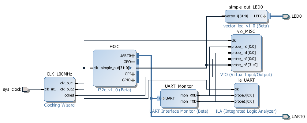
Vivado IPI Block Diagram for the f32c_demo. F32C is clocked at 100MHz, Memory configuration set to 128KByte or larger for all devices that have enough BRAM's, bit 0 of simple_out is connected to on-board LED. Optionally there may be FPGA debug IP Cores added, VIO and or ILA, in the example above is Logic Analyzer added on the UART (using UART_MON IP Core). Baud rate 115200.
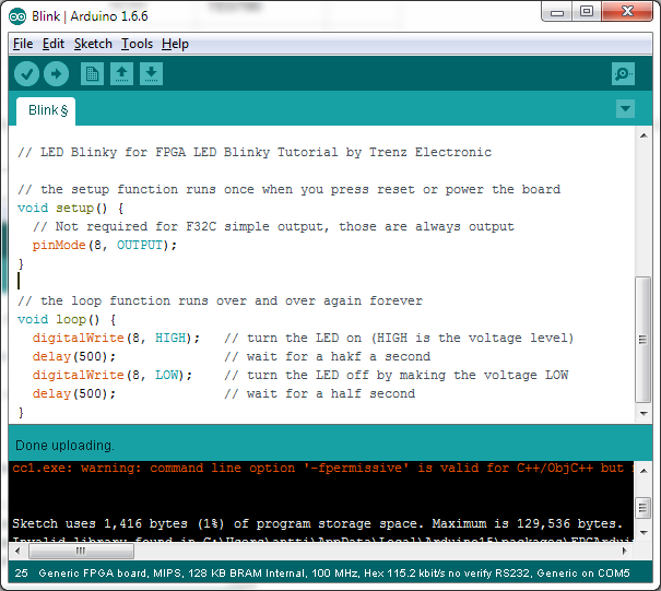
This is Arduino IDE screenshot after downloading LED Blinky sketch to F32C inside FPGA, selected generic FPGA board with 128K RAM and 100MHz Clock. After download the on-board LED on the FPGA/SoC SoM will blink.
Overview
Content Tools