Overview
This page describes in detail which software, and their respective versions, was used to generate und use the module demonstration. Further described is how to flash the Hardware and Software Design contained in the Demo Archieve onto the TEM0001. A brief usage introduction for each Demo is included.
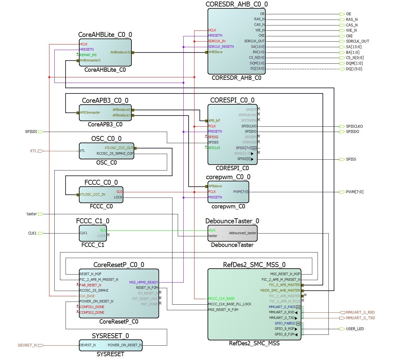
The Hardware Reference Design uses these Smartfusion 2 SoC, hard Arm® Cortex®-M3 Core, Soft SDRAM Core, Soft SPI Core, COM port, Real Time Clock and the on-board LEDs via a Soft PWM Core.
The Software Designs Hello World, SF2_GNU_SC4_pwm_slow_blink and SF2_GNU_SC4_rtc_time use the Hardware Design features to a different degree. Most notably is Hello World, which utializes all features of the Hardware and is very close to the modules production test.
Refer to TEM0001-Resources for the current online version of this manual and other available documentation.
Key Features
- Libero 2021.2 (FPGA IDE)
- SoftConsole 2021.1 (Software IDE)
- UART
- SDR
- eNVM
- User LED access
- Real Time Clock
Revision History
Table of Design Revision History
| Date | Libero | SoftConsole | Project Built | Authors | Description |
|---|---|---|---|---|---|
| 2021-12-15 | 2021.2 | 2021.1 | TEM0001_test-board_Libero-2021.2_20211215123500 .zip | Kilian Jahn |
|
| 2021-12-10 | 2021.2 | 2021.1 | TEM0001-test_board-Libero-2021.2_20211210112900 .zip | Kilian Jahn |
|
Release Notes and Know Issues
Non known so far.
Requirements
The Designs were created and tested in the following windows environment.
Software
Table of used Software and their Versions
| Software | Version | Note |
|---|---|---|
| Windows 10 | 21H1 - 19043 | |
| Libero Release | 2021.2 | |
| SoftConsole | 2021.1 | Included in the Libero installation |
| Microsemi Flash Pro 5 module driver | 2.10.0.0 | Utilize onboard programmer and USB / COM port connection. Included in the Libero installation |
| FTDI Driver for the TEM0002 module | 2.12.28.0 | |
| UART / COM-port terminal | Capturing the modules messages |
Hardware
Design supports following modules:
Table of Hardware Modules
| Module Model | Board Part Short Name | PCB Revision Support | DDR | embedded SRAM | embedded Flash | Notes |
|---|---|---|---|---|---|---|
| TEM0001-01A-010C | SMF2000 | REV01 | 8 MB | 64 kB | 256 kB | NA |
Additional hardware Requirements:
Table of Additional Hardware
| Additional Hardware | Notes |
|---|---|
| Demo host computer | Demo was created and tested on windows |
| Micro USB to USB Type A Cable | Power supply, JTAG: Programming the board, UART: Communication Interface to the board. |
Content
The Trenz Electronic Reference Designs and Demos are usable with the specified Microsemi Libero / SoftConsole version. Usage of a different Microsemi Libero / SoftConsole software versions is not recommended.Download
The download is a ZIP compressed archive, it needs to be extract before usage.
Recommendation :
The path of the extracted archiev is vital for all IDE's, therefore place the extracted archiev outside the user space, e.g. "c:\Extracted_Archieve" [ Access rights / Path length limit ].
Reference Designs / Demos are available via the following link:
Design Sources
Content of the zip archive "TEM0001_test-board_Libero-2021.2_20211215123500 .zip" :
Table of Design sources
| Type | Location | Notes |
|---|---|---|
| Libero | <zip archive> / Libero2021.2_Hardware-Design | Libero Project containing the modules |
| SoftConsole | <zip archive> / SoftConsole2021.1_Workspace_TEM0001 / helloWorld / SF2_GNU_SC4_pwm_slow_blink / SF2_GNU_SC4_rtc_time | SoftConsole Workspace
|
| SoftConsole | <zip archive> / SoftConsole2021.1_Workspace_TEM0001 / microsemi-cortex-m3.cfg | File for software debugging in |
| FlashPro Express | <zip archive> / FlashProExpress2021.2 / RefDes02 / RefDes02-HelloWorld / RefDes02-Zerocitation | Programming Files to use in FlashPro Express. Omittes the usage of Libero and SoftConsole for Programming.
|
Launch
Executing a Reference / Demo Design on a module requires the powering of it and a JTAG or UART Connection for Programming and Communication. Often the programming is a two fold process, where the first programming configures the FPGA and the second programming flashes Software code to be executed inside the FPGA / ARM processor.
Connecting
Variant without explicit power connector:
Connect the modules Micro-USB to your host pc, this enables the powering of the module and a simultaneous JTAG and UART connection .
Driver check
When the module is connected via USB cable to your demo host computer, in the Windows Device Manager appear the following three board driver related devices:
In section Ports (COM & LPT):
- FlashPro5 Port (ComX)
In section Universal Serial Bus controllers:
- USB FP5 Serial Converter A
- USB FP5 Serial Converter B
The Device Manager is accessible via "Right mouse click context menu" from the Windows Start Menu Button. When these devices are not visible, the driver installation through libero could be faulty.
Programming Hard and Software Designs
Before flashing any design to the module, open a terminal programm (e.g. PuTTY or SmarTTY) to the boards COM port, so that when the module restarts after programming, it's messages can be captured.
Programming Variant "IDE"
The Microsemi Hardware and Software Design Tools, Libero and SoftConsole, incorporate the abillity to edit, debug and program Hardware and Software Designs. This Programming Variant is for you, when you are interessted in this.
Programming the Hardware design
To program the Hardware Reference Design, start the FPGA Design IDE "Libero SoC v2021.2".
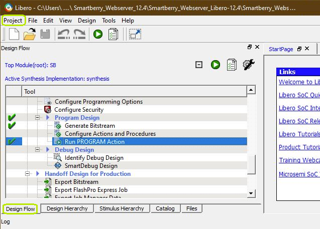
Libero GUI "Run PRGORAMM ACTION"
The Hardware Reference Design can be opened via "Project > Open Project" in the top right corner of Libero (picture above - upper green rectangle). A file dialogue opens, point the dialogue along to the extracted download folder containing the Hardware Design.
Disk :\ Path-to-the-Demo-archive \ Extracted ZIP-archive \ Libero-X.y_Hardware-Design\
Double left mouse click onto the project file "TEM0001_RefDesV02.prjx" to open it. The board is automatically selected and setup to be flashed by Libero.
In the upper left section of Libero, select the tab "Design Flow" (picture above - lover green rectangle) and flash it to the board via "Program Design > and double left mouse click onto "Run PROGRAM Action" (picture above - row with blue background).
Warnings should not affect the functionality of a Reference / Demo -Design.
Programming a Software project
Open SoftConsole and press "Browse..." near the right edge. A file dialogue opens, point the dialogue along the extracted download to the folder containing the SoftConsole Workspace.
Disk :\ Path-to-the-Demo-archive \ Extracted ZIP-archive \ SoftConsoleX.y_Workspace_TEM0001 \
Confirm your selectioin by pressing "Ok" , the dialogue closes, and open The SoftConsole by pressing "Launch"
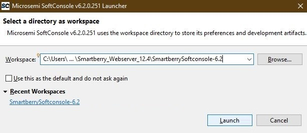
SoftConsole "Select the Workspace"
Subsequently the program opens and shows the software project's who are contained inside the workspace to the left, under "Project Explorer".
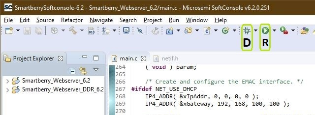
SoftConsole GUI
To simply run a Project, press the triangle right to the button marked with a "R" in the picture above and select a variant of the demo.
Pressing the triangle next to the button marked with "D" let you select which variant to be executed in debug mode.
Debug controls - Resume - Pause - Stop
SoftConsole "Debug controlls"
Switch between Debug and Code Writting perspective (upper right corner program window)
![]()
SoftConsole "Switch GUI layout"
Programming or Debugging a Software Design with the IDE SoftConsole needs to be manually stopped, in order to rerun it or to alter to a different Design.
Programming Variant "FlashPro Express"
When you just want to run a SoC Design, this is for you.
To program a Hardware and Software Design simultaneously, open FlashPro Express. Via left click onto Open .... in the section "Job Projects" open a file dialogue. Point to
Disk :\ Path-to-the-Demo-archive \ Extracted ZIP-archive \ FlashProExpressX.Y \ Desired Demo \ JobFile . pro
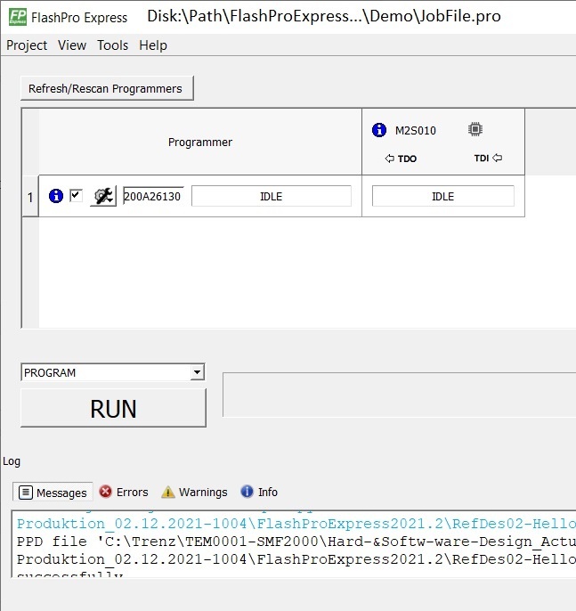
FlashPro Express GUI
To program the Design, press Run.
Hardware Reference Design - Libero
Smart Design
Block Design
Constrains
IO constraints
Clock constrains
Software Design - SoftConsole
Software Designs contained insode the workspace.
Hello World
The Hello World utializes all features of the Hardware. It runs an endless loop, which interacts with the modules periphy in each loop. It is very close to the modules production test.
Features
- Display the system time since power up
- Identifies SPI Flash IDs
- Tests different ~5 % of the SDR cells each loop and tracks the result above all loops
- Illuminates the 8 user LEDs in a row in selectable patterns [Counter, running & bouncing light]
- Illuminates all user LEDs while the user button is pressed
UART Messages
Hello World loop message
TEM0001-01B : "Hello world!" - Loop :    1

RTC-Time :
        0:00:00:00 (Day, hour, minute, second)

SPI Flash - Reding JEDEC specs :
        Device ID :       0X16
        Manufacturer ID : 0XEF, Winbond
        Device capacity : 0X17, 8 MB
        Device type :     0X40

SDRam test :
        Initializing 5% cells to random values, seed = 139
        Checking from 0XA0000000 to 0XA0400000 in steps of 19
        Result this loop - SUCCESSFULL
        All 1 Test Cycles - FLAWLESS
Interaction
- Press the User Button S2 to switch the illumination patterns
Demo SF2_GNU_SC4_pwm_slow_blink
This software design illuminates the User LED D10. The User LED D2 transitions between illuminated and off continuously.
Demo SF2_GNU_SC4_rtc_time
Resambles a clock with time and date. Time and Date can be set.
RTC time Initialization message
********************************************************************

************** SmartFusion2 RTC Calendar Time Example **************

********************************************************************

This example project reads the time from the SmartFusion2 RTC.

A simple command line interface allows the following operations:

  - Set the RTC time by pressing "t"

  - Set the RTC date by pressing "d"

--------------------------------------------------------------------


    Saturday  January   1  2000  (week 1) 00:00:34
Interaction
To edit the time press t or d for the date, confirm via Enter. The program alters to setup mode. Changing the values for hour, minute and second is done independently for each value, enter a valid value and press Enter. When all values are entered, the new values are accepted . A non valid value will terminate the setup mode.
Appx. A: Change History and Legal Notices
Document Change History
To get content of older revision got to "Change History" of this page and select older document revision number.
| Date | Document Revision | Authors | Description |
|---|---|---|---|
| |||
| -- | all | -- |
Document change history.
Legal Notices
Data Privacy
Please also note our data protection declaration at https://www.trenz-electronic.de/en/Data-protection-Privacy
Document Warranty
The material contained in this document is provided “as is” and is subject to being changed at any time without notice. Trenz Electronic does not warrant the accuracy and completeness of the materials in this document. Further, to the maximum extent permitted by applicable law, Trenz Electronic disclaims all warranties, either express or implied, with regard to this document and any information contained herein, including but not limited to the implied warranties of merchantability, fitness for a particular purpose or non infringement of intellectual property. Trenz Electronic shall not be liable for errors or for incidental or consequential damages in connection with the furnishing, use, or performance of this document or of any information contained herein.
Limitation of Liability
In no event will Trenz Electronic, its suppliers, or other third parties mentioned in this document be liable for any damages whatsoever (including, without limitation, those resulting from lost profits, lost data or business interruption) arising out of the use, inability to use, or the results of use of this document, any documents linked to this document, or the materials or information contained at any or all such documents. If your use of the materials or information from this document results in the need for servicing, repair or correction of equipment or data, you assume all costs thereof.
Copyright Notice
No part of this manual may be reproduced in any form or by any means (including electronic storage and retrieval or translation into a foreign language) without prior agreement and written consent from Trenz Electronic.
Technology Licenses
The hardware / firmware / software described in this document are furnished under a license and may be used /modified / copied only in accordance with the terms of such license.
Environmental Protection
To confront directly with the responsibility toward the environment, the global community and eventually also oneself. Such a resolution should be integral part not only of everybody's life. Also enterprises shall be conscious of their social responsibility and contribute to the preservation of our common living space. That is why Trenz Electronic invests in the protection of our Environment.
REACH, RoHS and WEEE
REACH
Trenz Electronic is a manufacturer and a distributor of electronic products. It is therefore a so called downstream user in the sense of REACH. The products we supply to you are solely non-chemical products (goods). Moreover and under normal and reasonably foreseeable circumstances of application, the goods supplied to you shall not release any substance. For that, Trenz Electronic is obliged to neither register nor to provide safety data sheet. According to present knowledge and to best of our knowledge, no SVHC (Substances of Very High Concern) on the Candidate List are contained in our products. Furthermore, we will immediately and unsolicited inform our customers in compliance with REACH - Article 33 if any substance present in our goods (above a concentration of 0,1 % weight by weight) will be classified as SVHC by the European Chemicals Agency (ECHA).
RoHS
Trenz Electronic GmbH herewith declares that all its products are developed, manufactured and distributed RoHS compliant.
WEEE
Information for users within the European Union in accordance with Directive 2002/96/EC of the European Parliament and of the Council of 27 January 2003 on waste electrical and electronic equipment (WEEE).
Users of electrical and electronic equipment in private households are required not to dispose of waste electrical and electronic equipment as unsorted municipal waste and to collect such waste electrical and electronic equipment separately. By the 13 August 2005, Member States shall have ensured that systems are set up allowing final holders and distributors to return waste electrical and electronic equipment at least free of charge. Member States shall ensure the availability and accessibility of the necessary collection facilities. Separate collection is the precondition to ensure specific treatment and recycling of waste electrical and electronic equipment and is necessary to achieve the chosen level of protection of human health and the environment in the European Union. Consumers have to actively contribute to the success of such collection and the return of waste electrical and electronic equipment. Presence of hazardous substances in electrical and electronic equipment results in potential effects on the environment and human health. The symbol consisting of the crossed-out wheeled bin indicates separate collection for waste electrical and electronic equipment.
Trenz Electronic is registered under WEEE-Reg.-Nr. DE97922676.
Table of contents
Overview
Content Tools