Page History
...
| HTML |
|---|
<!-- Add Basic Key Features of the design (should be tested) --> |
| Excerpt |
|---|
|
Revision History
| HTML |
|---|
<!-- - Add changes from design - Export PDF to download, if vivado revision is changed! --> |
...
| Module Model | Board Part Short Name | PCB Revision Support | DDR | QSPI Flash | Others | Notes |
|---|
Design supports following carriers:
| TE0725-03-15-1C | 15_1c | REV01, REV02, REV03 | --- | 32 | 8MB HypeRAM | |
| TE0725-03-35-2C | 35_2c | REV01, REV02, REV03 | Carrier Model | Notes--- |
|---|
Additional HW Requirements:
| 32 | 8MB HypeRAM | Additional Hardware | Notes
|---|
Content
| HTML |
|---|
<!--
Remove unused content
--> |
For general structure and of the reference design, see Project Delivery
Design Sources
...
| TE0725-03-100-2C | 100_2c | REV01, REV02, REV03 | --- | 32 | 8MB HypeRAM | |
| TE0725-03-100-2CF | 100_2c | REV01, REV02, REV03 | --- | 32 | 8MB HypeRAM | POF assembled |
| TE0725-03-100-2I9 | 100_2i | REV01, REV02, REV03 | --- | 32 | 8MB HypeRAM |
Design supports following carriers:
| Carrier Model | Notes |
|---|---|
| --- |
Additional HW Requirements:
| Additional Hardware | Notes |
|---|---|
| TE0790 JTAG Programmer | It's not recommended to use TE0790 for power supply( TE0790 TRM#PowerandPower-OnSequence) |
| External power supply |
Content
| HTML |
|---|
<!--
Remove unused content
--> |
For general structure and of the reference design, see Project Delivery
Design Sources
| Type | Location | Notes |
|---|---|---|
| Vivado | <design name>/block_design <design name>/constraints <design name>/ip_lib | Vivado Project will be generated by TE Scripts |
| SDK/HSI | <design name>/sw_lib | Additional Software Template for SDK/HSI and apps_list.csv with settings for HSI |
Additional Sources
| Type | Location | Notes |
|---|
Prebuilt
| HTML |
|---|
<!--

<table width="100%">
<tr> <th>File |
Additional Sources
...
Prebuilt
| HTML |
|---|
<!-- <table width="100%"> <tr> <th>File </th> <th>File-Extension</th> <th>Description </th> </tr> <tr> <td>BIF-File </td> <td>*.bif </td> <td>File with description to generate Bin-File </td> </tr> <tr> <td>BIN-File </td> <td>*.bin </td> <td>Flash Configuration File with Boot-Image (Zynq-FPGAs) </td> </tr> <tr> <td>BIT-File </td> <td>*.bit </td> <td>FPGA Configuration File </td> </tr> <tr> <td>DebugProbes-File </td> <td>*.ltx </td> <td>Definition File for Vivado/Vivado Labtools Debugging Interface </td> </tr> <tr> <td>Debian SD-Image </td> <td>*.img </td> <td>Debian Image for SD-Card </td> </tr> <tr> <td>Diverse Reports </td> <td> --- </td> <td>Report files in different formats </td> </tr> <tr> <td>Hardware-Platform-Specification-Files</td> <td>*.hdf </td> <td>Exported Vivado Hardware Specification for SDK/HSI </td> </tr> <tr> <td>LabTools Project-File </td> <td>*.lpr </td> <td>Vivado Labtools Project File </td> </tr> <tr> <td>MCS-File </td> <td>*.mcs </td> <td>Flash Configuration File with Boot-Image (MicroBlaze or FPGA part only) </td> </tr> <tr> <td>MMI-File </td> <td>*.mmi </td> <td>File with BRAM-Location to generate MCS or BIT-File with *.elf content (MicroBlaze only) </td> </tr> <tr> <td>OS-Image </td> <td>*.ub </td> <td>Image with Linux Kernel (On Petalinux optional with Devicetree and RAM-Disk) </td> </tr> <tr> <td>Software-Application-File </td> <td>*.elf </td> <td>Software Application for Zynq or MicroBlaze Processor Systems </td> </tr> <tr> <td>SREC-File </td> <td>*.srec </td> <td>Converted Software Application for MicroBlaze Processor Systems </td> </tr> </table> --> |
...
Reference Design is available on:
Design Flow
| HTML |
|---|
<!-- Basic Design Steps Add/ Remove project specific --> |
...
TE Scripts are only needed to generate the vivado project, all other additional steps are optional and can also executed by Xilinx Vivado/SDK GUI. For currently Scripts limitations on Win and Linux OS see: Project Delivery Currently limitations of functionality
- _create_win_setup.cmd/_create_linux_setup.sh and follow instructions on shell:
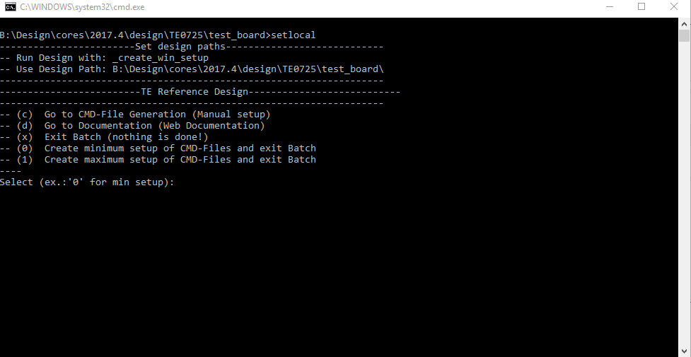
- Press 0 and enter for minimum setup
- (optional Win OS) Generate Virtual Drive or use short directory for the reference design (for example x:\<design name>)
- Create Project
- Select correct device and Xilinx install path on "design_basic_settings.cmd" and create Vivado project with "vivado_create_project_guimode.cmd"
Note: Select correct one, see TE Board Part Files
- Select correct device and Xilinx install path on "design_basic_settings.cmd" and create Vivado project with "vivado_create_project_guimode.cmd"
- Create HDF and export to prebuilt folder
- Run on Vivado TCL: TE::hw_build_design -export_prebuilt
Note: Script generate design and export files into \prebuilt\hardware\<short dir>. Use GUI is the same, except file export to prebuilt folder
- Run on Vivado TCL: TE::hw_build_design -export_prebuilt
- _create_win_setup.cmd/_create_linux_setup.sh and follow instructions on shell:
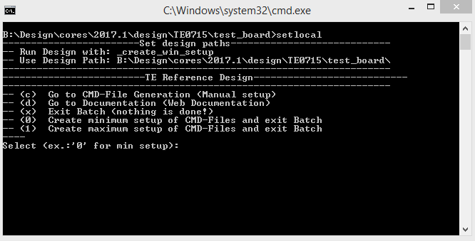
- Press 0 and enter for minimum setup
- (optional Win OS) Generate Virtual Drive or use short directory for the reference design (for example x:\<design name>)
- Create Project
- Select correct device and Xilinx install path on "design_basic_settings.cmd" and create Vivado project with "vivado_create_project_guimode.cmd"
Note: Select correct one, see TE Board Part Files
- Select correct device and Xilinx install path on "design_basic_settings.cmd" and create Vivado project with "vivado_create_project_guimode.cmd"
- Create HDF and export to prebuilt folder
- Run on Vivado TCL: TE::hw_build_design -export_prebuilt
Note: Script generate design and export files into \prebuilt\hardware\<short dir>. Use GUI is the same, except file export to prebuilt folder
- Run on Vivado TCL: TE::hw_build_design -export_prebuilt
- Create Linux (uboot.elf and image.ub) with exported HDF
- HDF is exported to "prebuilt\hardware\<short name>"
Note: HW Export from Vivado GUI create another path as default workspace. - Create Linux images on VM, see PetaLinux KICKstart
- Use TE Template from /os/petalinux
Note: run init_config.sh before you start petalinux config. This will set correct temporary path variable.
- Use TE Template from /os/petalinux
- HDF is exported to "prebuilt\hardware\<short name>"
- Add Linux files (uboot.elf and image.ub) to prebuilt folder
- "prebuilt\os\petalinux\default" or "prebuilt\os\petalinux\<short name>"
Notes: Scripts select "prebuilt\os\petalinux\<short name>", if exist, otherwise "prebuilt\os\petalinux\default"
- "prebuilt\os\petalinux\default" or "prebuilt\os\petalinux\<short name>"
- Generate Programming Files with HSI/SDK
- Run on Vivado TCL: TE::sw_run_hsi
Note: Scripts generate applications and bootable files, which are defined in "sw_lib\apps_list.csv" - (alternative) Start SDK with Vivado GUI or start with TE Scripts on Vivado TCL: TE::sw_run_sdk
Note: See SDK Projects
- Run on Vivado TCL: TE::sw_run_hsi
SDSoC (only tested on Win OS)
- Generate Platform Project or use prebuilt from download
- ...
Launch
Programming
| HTML |
|---|
<!--
Description of Block Design, Constrains...
BD Pictures from Export...
--> |
| Note |
|---|
Check Module and Carrier TRMs for proper HW configuration before you try any design. |
Xilinx documentation for programming and debugging: Vivado/SDK/SDSoC-Xilinx Software Programming and Debugging
QSPI
Optional for Boot.bin on QSPI Flash and image.ub on SD.
- Connect JTAG and power on carrier with module
- Open Vivado Project with "vivado_open_existing_project_guimode.cmd" or if not created, create with "vivado_create_project_guimode.cmd"
- Type on Vivado TCL Console: TE::pr_program_flash_binfile -swapp u-boot
Note: To program with SDK/Vivado GUI, use special FSBL (zynqmp_fsbl_flash) on setup - Copy image.ub on SD-Card
- For correct prebuilt file location, see <design_name>/prebuilt/readme_file_location.txt
- Insert SD-Card
SD
...
- For correct prebuilt file location, see <design_name>/prebuilt/readme_file_location.txt
...
- Depends on Carrier, see carrier TRM.
- Copy Application (hello_te0711.elf) into \firmware\microblaze_0\
- Regenerate Design:
- Run on Vivado TCL: TE::hw_build_design -export_prebuilt
Note: App from Firmware folder will be add into BlockRAM. If you add other app, you must select *.elf manually on Vivado - (alternative) Use SDK or Vivado to update generate Bitfile with new Application and regenerate mcs manually.
- Run on Vivado TCL: TE::hw_build_design -export_prebuilt
Launch
Programming
| HTML |
|---|
<!--
Description of Block Design, Constrains...
BD Pictures from Export...
--> |
| Note |
|---|
Check Module and Carrier TRMs for proper HW configuration before you try any design. |
Xilinx documentation for programming and debugging: Vivado/SDK/SDSoC-Xilinx Software Programming and Debugging
QSPI
- Connect JTAG and power on PCB
- (if not done) Select correct device and Xilinx install path on "design_basic_settings.cmd" and create Vivado project with "vivado_create_project_guimode.cmd" or open with "vivado_open_project_guimode.cmd", if generated.
- Type on Vivado Console: TE::pr_program_flash_mcsfile
Note: Alternative use SDK or setup Flash on Vivado manually - Reboot (if not done automatically)
SD
Not used on this Example
...
.
JTAG
Not used on this Example.
...
- Prepare HW like described on section Programming
- Connect UART USB (most cases same as JTAG)Select SD Card as Boot Mode
Note: See TRM of the Carrier, which is used. - Power On PCB
Note:
1. Zynq Boot ROM loads FSBL from SD into OCM, 2. FSBL loads U-boot from SD into DDR, 3. U-boot load Linux from SD into DDR
...
FPGA Loads Bitfile from Flash
UART
- Open Serial Console (e.g. putty)
- Speed: 115200
- COM Port: Win OS, see device manager, Linux OS see dmesg |grep tty (UART is *USB1)
- Linux Console:
Note: Wait until Linux boot finished For Linux Login use:- User Name: root
- Password: root
Vivado HW Manager
SI5338_CLK0 Counter:
...
- : 115200
- COM Port: Win OS, see device manager, Linux OS see dmesg |grep tty (UART is *USB1)
- Uart Console:
Hello TE0725 will run on endless loop.
System Design - Vivado
| HTML |
|---|
<!-- Description of Block Design, Constrains... BD Pictures from Export... --> |
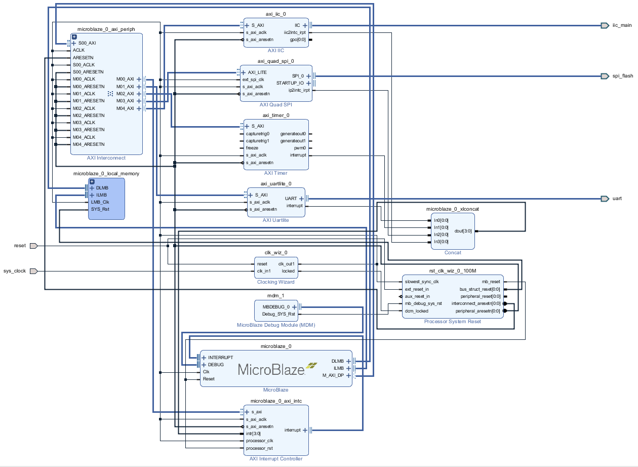
Block Design
...
Constrains
Basic module constrains
| Code Block | ||||
|---|---|---|---|---|
| ||||
set_property BITSTREAM.GENERAL.COMPRESS TRUE [current_design] set_property BITSTREAM.CONFIG.CONFIGRATE 66 [current_design] set_property CONFIG_VOLTAGE 3.3 [current_design] set_property BITSTREAM.GENERAL.COMPRESS TRUECFGBVS VCCO [current_design] set_property BITSTREAM.CONFIG.SPI_32BIT_VOLTAGEADDR 3.3YES [current_design] set_property CFGBVS VCCOBITSTREAM.CONFIG.SPI_BUSWIDTH 4 [current_design] set_property BITSTREAM.CONFIG.USR_ACCESSM1PIN TIMESTAMPPULLNONE [current_design] |
Design specific constrain
| Code Block | ||||
|---|---|---|---|---|
| ||||
set_property PACKAGE_PIN K2BITSTREAM.CONFIG.M2PIN PULLNONE [get_ports {fclk[0]}current_design] set_property IOSTANDARD LVCMOS18BITSTREAM.CONFIG.M0PIN PULLNONE [get_ports {fclk[0]}]current_design] set_property CLOCK_DEDICATED_ROUTE FALSE [get_nets fclk_IBUF[0]]BITSTREAM.CONFIG.USR_ACCESS TIMESTAMP [current_design] |
Design specific constrain
Software Design - SDK/HSI
...
Hello World as endless loop.
Additional Software
| HTML |
|---|
<!-- Add Description for other Software, for example SI CLK Builder ... --> |
...
Overview
Content Tools