Page History
...
Quartus places the folder db, two files HPSexample.qpf and HPSexample.qsf into the project folder
and the setup is accomplished.

Plattform Designer
- Use the Plattform Designer to configure the resources needed to boot the HPS
(System Memory and SD card access)
- Connect the basic interfaces (Uart and i²c) of the HPS to the board resources
- Compile the project to get the required files and folders for the next steps
File → New → Qsys System File
Program - plattform Designer opens
Upper left column - Search field type in hps
HPSexample.sopinfo / PlattformEditorHPS.qip file and (hps_isw_)handoff folder
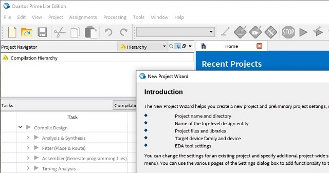
The Plattform Designer can be opened via Tools → Plattform Designer and later on, the output must be added into
project. Instead, both steps can be performed through adding a Qsys System File to the project.
File → New , select Qsys System File and press OK, the Plattform Designer opens in a new window.
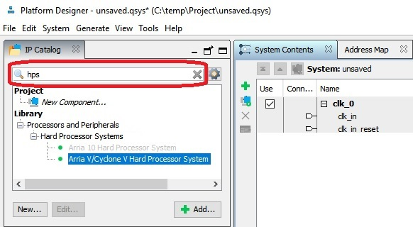
To configure the resources and interfaces of the HPS, it needs first to be added into the system,
Type into the search field in the upper left column hps.
Select Arria V/Cyclone V Hard Processor System via double click from the tree:
Select below: Library - Processors and Peripherals - Hard Processor Systems - Arria V/Cyclone V Hard Processor Systemvia double click

The window - Arria V/Cyclone V Hard Processor System - hps_0 - opens. To setup the peripheral of the HPS ,
transfer everything of the following list into the tabs mentioned. Everything not mentioned must be left untouched.A new window opens
Tab FPGA Interface:
Uncheck Enable MPU standby and event signals (default)
...
Tab Peripheral Pins:
Quad SPI Flash Controller - QSPI pin: HPS I/O Set 0
SD/MMC Controller - SDIO pin: HPS I/O Set 0 - SDIO mode: 4-bit Data
USB Controllers
SPI Controllers
UART Controllers - UART0 pin: HPS I/O Set 0 - UART0 mode: no Flow Control
I2C Controllers - I2C0 pin: HPS I/O Set 1 - I2C1 pin: HPS I/O Set 0
Can Controllers
Tab HPS Clocks:
As is / Accept the default values (for both subtabs)
...
Tab SDRAM - Subtask - Memory Timing:
tIS (base): 180 ps tIH (base): 140 ps tDS (base) 30 ps tDH (base): 65 psps
tDQSQ: 100 ps tQH 0.38 cycles tDQSCK_ 225 ps
tDQSS: 0.27 cycles tQSH: 0.4 cycles tDSH:0.18 cycles tDSS: 0.18 cycles
tINIT: 500 us tMRD (tMRW): 4 cycles
tRAS: 35.0 ns tRCD: 13.75 ns tRP: 13.75 ns tREFI (tREFIab): 7.8 us tRFC (tRFCab): 350.0 ns tWR: 15.0 ns
tWTR: 4 cycles tFAW: 40 ns tRRD: 12.0 ns tRTP: 12.0 n
Tab SDRAM - Subtask - Board Settings:
Board Skews
Maximum CK delay to DIMM/device: 0.03
Maximum DQA delay to DIMM/device: 0.02
Minimum delay between CK and DQS: 0.09
Maximum delay between CK and DQS: 0.16
Maximum skew within DQS group: 0.01
Maximum skew between DQS groups: 0.08Average delay difference between DQ and DQA: 0.0
Maximum skew within address and command bus: 0.03Average delay difference between address and command and CK: 0.0
Bottom left → Click Finish
Click Finish in the bottom left to close the window - Arria V/Cyclone V Hard Processor System - hps_0 .
To change or correct these parameters later click onto the IP cores top entry in the list in the
Tab tab System Control Contents - Column Name - hps_0.
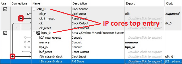
Add Connections via klicking clicking into the the circle MARKED marked with a red rectangle in th picture above.
hps_0 - h2f_reset → reset → clk_0 - clk_in_reset
clk_0 - clk → clk → hps_0 - f2h_sdram0_data
Is this Step NEEDED?!?!?
...
Overview
Content Tools