Page History
...
- _create_win_setup.cmd/_create_linux_setup.sh and follow instructions on shell:
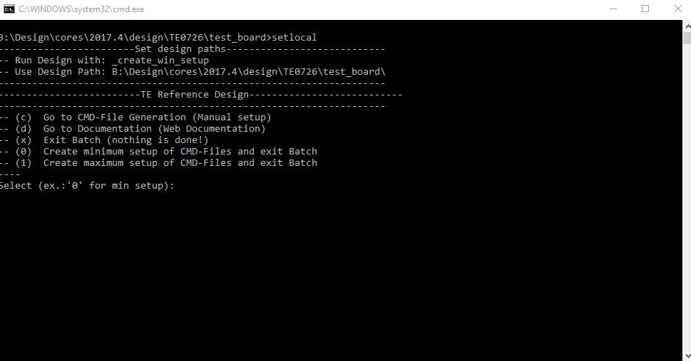
- Press 0 and enter to start "Module Selection Guide"
- (optional Win OS) Generate Virtual Drive or use short directory for the reference design (for example x:\<design name>)
- Create Project (follow instruction of the product selection guide), settings file will be configured automatically during this process
- (optional for manual changes) Select correct device and Xilinx install path on "design_basic_settings.cmd" and create Vivado project with "vivado_create_project_guimode.cmd"
Note: Select correct one, see TE Board Part Files
- (optional for manual changes) Select correct device and Xilinx install path on "design_basic_settings.cmd" and create Vivado project with "vivado_create_project_guimode.cmd"
- Create XSA and export to prebuilt folder
- Run on Vivado TCL: TE::hw_build_design -export_prebuilt
Note: Script generate design and export files into \prebuilt\hardware\<short dir>. Use GUI is the same, except file export to prebuilt folder
- Run on Vivado TCL: TE::hw_build_design -export_prebuilt
- Create Linux (uboot.elf and image.ub) with exported XSA
- XSA is exported to "prebuilt\hardware\<short name>"
Note: HW Export from Vivado GUI create another path as default workspace. - Create Linux images on VM, see PetaLinux KICKstart
- Use TE Template from /os/petalinux_<ramdisk or ubuntu>
- (optional) Build the Ubuntu image file with executing the "mkubuntu_jupyter.sh" file in Linux Terminal
- ramdisk
- XSA is exported to "prebuilt\hardware\<short name>"
- Add Linux files (uboot.elf and image.ub) to prebuilt folder
- "prebuilt\os\petalinux\<DDR size>" or "prebuilt\os\petalinux\<short name>"
Notes: Scripts select "prebuilt\os\petalinux\<DDR size>", if exist, otherwise "prebuilt\os\petalinux\<short name>"
- "prebuilt\os\petalinux\<DDR size>" or "prebuilt\os\petalinux\<short name>"
- Generate Programming Files with Vitis
- Run on Vivado TCL: TE::sw_run_vitis -all
Note: Scripts generate applications and bootable files, which are defined in "sw_lib\apps_list.csv" - (alternative) Start SDK with Vivado GUI or start with TE Scripts on Vivado TCL: TE::sw_run_vitis
Note: TCL scripts generate also platform project, this must be done manuelly in case GUI is used. See Vitis
- Run on Vivado TCL: TE::sw_run_vitis -all
...
- Connect JTAG and power on the carrier with module
- Open Vivado Project with "vivado_open_existing_project_guimode.cmd" or if not created, create with "vivado_create_project_guimode.cmd"
- Type on Vivado TCL Console: TE::pr_program_flash_binfile -swapp u-boot
Note: To program with Vitis GUI, use special FSBL (zynqmp_fsbl_flash) on setup
optional "TE::pr_program_flash_binfile -swapp hello_te0726" possibleFormat the SD Card with SD Card Formatter or other tool - (optional) Write the Debian image or Ubuntu image file on SD Card with Win32DiskImager
- Copy Petalinux image.ub on SD-Card
- use files from (<project foler>/_binaries_<Articel Name>)/boot_linux from generated binary folder,see: Get prebuilt boot binaries
- For correct prebuilt file location, see <design_name>/prebuilt/readme_file_location.txt
- Important: Do not copy Boot.bin on SD(is not used see SD note), only other files.
- Insert SD-Card
...
- Open Serial Console (e.g. putty)
- Speed: 115200
- COM Port: Win OS, see device manager, Linux OS see dmesg |grep tty (UART is *USB1)
- Linux Console:
Note: Wait until Linux boot finished For Linux Login use:- User Name: root
- Password: root
Note: Wait until Linux boot finished For Linux Login use:- User Name: root
- Password: root
- You can use a Linux shell now.I2C 1 Bus type: i2cdetect -y -r 5
Bus 0...5 possible- ETH0 works with udhcpc
- USB: insert USB device
- When using ubuntu as root file system, GUI starts automatically.
- (optional) Ubuntu Desktop
- Web Browser Mozilla firefox can be used.
- Audio or Vider file can also be performed directly in GUI.
- To know the board ip address, you can enter the following command:
- ifconfig
- You can
- ifconfig
- You can find the ip address in :
- inet addr: <Board Ip Address>
- ifconfig
- Use the following command to connect the board to Jupyter Server:
jupyter notebook --ip=<Board Ip Address> --port=<An optional Number 0-9999> --NotebookApp.token='' --allow-root &
- For example : jupyter notebook --ip=192.168.2.1 --port=8888 --NotebookApp.token='' --allow-root &
- In Web Browser, open a page with the following address:
- <Board IP Address>:<Port Number> --→ For example 192.168.2.1:8888
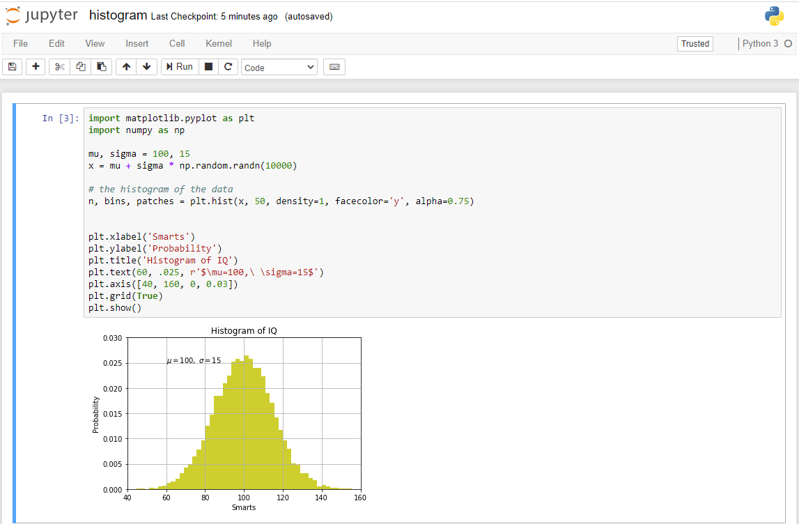
- Written code in Python can now be executed.
Example code:
| Code Block | ||
|---|---|---|
| ||
import matplotlib.pyplot as plt import numpy as np mu, sigma = 100, 15 x = mu + sigma * np.random.randn(10000) # the histogram of the data n, bins, patches = plt.hist(x, 50, density=1, facecolor='g', alpha=0.75) plt.xlabel('Smarts') plt.ylabel('Probability') plt.title('Histogram of IQ') plt.text(60, .025, r'$\mu=100,\ \sigma=15$') plt.axis([40, 160, 0, 0.03]) plt.grid(True) plt.show() |
System Design - Vivado
| Page properties | ||||
|---|---|---|---|---|
| ||||
Note:
|
...
Overview
Content Tools