| Page properties |
|---|
|
Design Name always "TE Series Name" + Design name, for example "TEI0006 TEM0007 Test Board" | Date | Version | Changes | Author |
|---|
2022| 2024- | 06| 04- | 15| 16 | 2| 1.2 | - add 'QSPI-Boot mode'
- add 'Get prebuilt boot binaries'
- changed SD-Boot mode chapter
- 'Device Tree' chapter expanded
| TD | | 2022-04-21 | 2.1 | | TD | | 2022-02-28 | 2.0 | - add yocto to
- Overview → Key Features
- Overview → Requirements
- Design Flow
- Launch
- add section 'Software Design - Yocto'
| TD | | 2021-06-15 | 1.2 | - table of content view
- template history
- placed a horizontal separation line under each chapter heading
- replaced <design name> by <project folder>
- changed title-alignment for tables from left to center
- update 19.x to 20.x
| JH,TD | | 2020-11-24 | 1.1 | - add fix table of content
- add table size as macro
| JH | | -- | 1.0 | -- | -- |
|
| Page properties |
|---|
|
Important General Note:
Export PDF to download, if quartus revision is changed!
Designate all graphics and pictures with a number and a description, Use "Scroll Title" macro
Use "Scroll Title" macro for pictures and table labels. Figure number must be set manually at the moment (automatically enumeration is planned by scrollPDF)Figure template (note: inner scroll ignore/only only with drawIO object):
- Modification of the document
- Such topics same as Hart Software Services is added.
| MC | | 2024-02-14 | 1.1 | Conversion into template | KJ | | 2023-11-13 | 1.0 | Initial Template based on Intel/AMD template initial used by TEM0007 testboard copy | MC/JH |
|
| Page properties |
|---|
|
Important General Note: Export PDF to download, if quartus revision is changed! Designate all graphics and pictures with a number and a description, Use "Scroll Title" macro - Use "Scroll Title" macro for pictures and table labels. Figure number must be set manually at the moment (automatically enumeration is planned by scrollPDF)
- ...
|
Overview
| Scroll Ignore |
|---|
| scroll-pdf | true |
|---|
| scroll-office | true |
|---|
| scroll-chm | true |
|---|
| scroll-docbook | true |
|---|
| scroll-eclipsehelp | true |
|---|
| scroll-epub | true |
|---|
| scroll-html | true |
|---|
|
|
| Scroll Title |
|---|
| anchor | Figure_xyz |
|---|
| title | Text |
|---|
|
| Scroll Ignore |
|---|
Create DrawIO object here: Attention if you copy from other page, use |
| Scroll Only |
|---|
image link to the generate DrawIO PNG file of this page. This is a workaround until scroll pdf export bug is fixed |
Table template:
- Layout macro can be use for landscape of large tables
- Set column width manually(can be used for small tables to fit over whole page) or leave empty (automatically)
| Scroll Title |
|---|
|
| Scroll Table Layout |
|---|
| orientation | portrait |
|---|
| sortDirection | ASC |
|---|
| repeatTableHeaders | default |
|---|
style | widths | | sortByColumn | 1 |
|---|
| sortEnabled | false |
|---|
| cellHighlighting | true |
|---|
| Example | Comment |
|---|
| 1 | 2 |
...Overview
| Scroll Ignore |
|---|
| scroll-pdf | true |
|---|
| scroll-office | true |
|---|
| scroll-chm | true |
|---|
| scroll-docbook | true |
|---|
| scroll-eclipsehelp | true |
|---|
| scroll-epub | true |
|---|
| scroll-html | true |
|---|
|
| Page properties |
|---|
|
Notes : |
Refer to http://trenz.org/tem0007-info for the current online version of this manual and other available documentation.
Key Features
| Page properties |
|---|
|
Notes : - Add basic key futures, which can be tested with the design
|
| Excerpt |
|---|
- Libero SoC v2022v2023.21
- SoftConsole v2022.2-RISC-V-747
- PolarfireSoC MSS Configurator v2022v2023.21
- HSS (Hardware System Service)
- Yocto
- UART
- v2023.02
- Microchip polarfire SoC BSP v2022.11
- FPExpress v2023.1
- Linux distribution BSP: "Yocto Kirkstone"
- UART
- ETH
- USB
- I2C
- QSPI flash
- DDR3 LPDDR4 memoryUser LED
|
Revision History
| Page properties |
|---|
|
Notes : - add Add every update file on the download
- add Add design changes on description
|
| Scroll Title |
|---|
| anchor | Table_DRH |
|---|
| title-alignment | center |
|---|
| title | Design Revision History |
|---|
|
| Scroll Table Layout |
|---|
| orientation | portrait |
|---|
| sortDirection | ASC |
|---|
| repeatTableHeaders | default |
|---|
| style | |
|---|
| widths | |
|---|
| sortByColumn | 1 |
|---|
| sortEnabled | false |
|---|
| cellHighlighting | true |
|---|
|
| Date | Libero SoC | Project Built | Authors | Description |
|---|
2023-30v2022.2-17
| v2023.1
| TEM0007-test_board_noprebuilt-libero_23.1-20240417101518.zip
TEM0007-test_board-libero_23.1-20240417101518.zip | Mohsen Chamanbaz
|
| |
Release Notes and Know Issues
| Page properties |
|---|
|
Notes :- add known Design issues and general notes for the current revision
- do not delete known issue, add fixed version time stamp if issue fixed
|
| Scroll Title |
|---|
| anchor | Table_KI |
|---|
| title-alignment | center |
|---|
| title | Known Issues |
|---|
|
- Release for more variants
- The design is matched to new carrier board TEB2000.
| 2023-11-13
| v2023.1
| TEM0007-test_board_noprebuilt-libero_23.1-20231113135744.zip
TEM0007-test_board-libero_23.1-20231113135744.zip
| Mohsen Chamanbaz
| - Clock frequency of LPDDR4 reduced to 500MHz.
- USB and ethernet phys will be reset while booting.
| | 2023-09-07 | v2023.1 | TEM0007-test_board_noprebuilt-libero_23.1-20230907135657.zip
TEM0007-test_board-libero_23.1-20230907135657.zip | Mohsen Chamanbaz | |
|
Release Notes and Know Issues
| Scroll Table Layout |
|---|
| orientation | portrait |
|---|
| sortDirection | ASC |
|---|
| repeatTableHeaders | default |
|---|
style | widths | | sortByColumn | 1 |
|---|
| sortEnabled | false |
|---|
| cellHighlighting | true |
|---|
| Issues | Description | Workaround | To be fixed version |
|---|
| No known issues | --- | --- | --- |
Requirements
Software| Page properties |
|---|
|
Notes :- list of software which was used to generate the design
- Add known Design issues and general notes for the current revision
- Do not delete known issue, add fixed version time stamp if issue fixed
|
| Scroll Title |
|---|
| Scroll Title |
|---|
| anchor | Table_SWKI |
|---|
| title-alignment | center |
|---|
| title | SoftwareKnown Issues |
|---|
|
| Scroll Table Layout |
|---|
| orientation | portrait |
|---|
| sortDirection | ASC |
|---|
| repeatTableHeaders | default |
|---|
| style | |
|---|
| widths | |
|---|
| sortByColumn | 1 |
|---|
| sortEnabled | false |
|---|
| cellHighlighting | true |
|---|
|
SoftwareVersion| Note | | Libero SoC | v2022.2 | needed | | SoftConsole | v2022.2 | needed | | PolarfireSoC MSS Configurator | v2022.2 | needed | | Yocto | Kirkstone | needed (more information: Yocto KICKstart#Used source files) | |
Hardware
| Workaround | To be fixed version |
|---|
| No known issues | --- | --- | --- |
|
Requirements
Software
| Page properties |
|---|
|
Notes : - list List of hardware software which was used to generate the design
- mark the module and carrier board, which was used tested with an *
|
Complete List is available on <project folder>/board_files/*_board_files.csv
Design supports following modules:
| Scroll Title |
|---|
|
| Scroll Title |
|---|
| anchor | Table_HWM |
|---|
| title-alignment | center |
|---|
| title | Hardware ModulesSoftware |
|---|
|
| Scroll Table Layout |
|---|
| orientation | portrait |
|---|
| sortDirection | ASC |
|---|
| repeatTableHeaders | default | style |
|---|
| widths | sortByColumn | 1 |
|---|
| sortEnabled | false |
|---|
| cellHighlighting | true |
|---|
|
|
| Module Model | Board Part Short Name | Yocto Machine Name | PCB Revision Support | DDR | QSPI Flash | EMMC | Others | Notes |
|---|
*used as reference
Design supports following carriers:
| Scroll Title |
|---|
| anchor | Table_HWC |
|---|
| title-alignment | center |
|---|
| title | Hardware Carrier |
|---|
|
| Software | Version | Note |
|---|
| Libero SoC | v2023.1 | needed for generating / viewing / modifying the hardware design | FPExpress
| v2023.1 | needed. Included within Libero SoC installation or as a standalone application . | | SoftConsole | v2022.2 | needed for generating / viewing / modifying the software design | | PolarfireSoC MSS Configurator | v2023.1 | needed for configuration of MSS | | Linux distribution "Yocto" | Kirkstone | needed |
|
Additional software requirement
| Scroll Table Layout |
|---|
| orientation | portrait |
|---|
| sortDirection | ASC |
|---|
| repeatTableHeaders | default |
|---|
style | widths | | sortByColumn | 1 |
|---|
| sortEnabled | false |
|---|
| cellHighlighting | true |
|---|
| Carrier Model | Notes |
|---|
--- | *used as reference
Additional HW Requirements:| Scroll Title |
|---|
| anchor | Table_AHWSW |
|---|
| title-alignment | center |
|---|
| title | Additional HardwareSoftware Requirement |
|---|
|
| Scroll Table Layout |
|---|
| orientation | portrait |
|---|
| sortDirection | ASC |
|---|
| repeatTableHeaders | default | style | widths |
|---|
| sortByColumn | 1 |
|---|
| sortEnabled | false |
|---|
| cellHighlighting | true |
|---|
|
| Requirement | Additional HardwareVersion | Notes |
|---|
| USB cable for JTAG/UART | Check Carrier Board and Programmer for correct type |
*used as reference |
Content| Note |
|---|
| Hart Software Services | v2023.02 | needed | | Microchip PolarFire SoC Yocto BSP (meta-polarfire-soc-yocto-bsp) | v2022.11 | needed |
|
Hardware
For general structure and usage of the reference design, see Project Delivery - Intel devices
Design Sources
- List of hardware which was used to generate the design
- Mark the module and carrier board, which was used tested with an *
|
Complete List is available on <project folder>/board_files/*_board_files.csv
Design supports following modules:
| Scroll Titlescroll-title |
|---|
| anchor | Table_DSHWM |
|---|
| title-alignment | center |
|---|
| title | Design sourcesHardware Modules |
|---|
|
| Scroll Table Layout |
|---|
| orientation | portrait |
|---|
| sortDirection | ASC |
|---|
| repeatTableHeaders | default |
|---|
| style | |
|---|
| widths | |
|---|
| sortByColumn | 1 |
|---|
| sortEnabled | false |
|---|
| cellHighlighting | true |
|---|
|
| Module Model | Board Part Short Name | Yocto Machine Name | PCB Revision Support | DDR | QSPI Flash | EMMC | Others | Type | Location | Notes |
|---|
| Quartus | <project folder>/source_files/quartus <project folder>/source_files/<Board Part Short Name>/quartus | Quartus project will be generated by TE Scripts (Optional) Source files for specific assembly variants | | Software | <project folder>/source_files/software <project folder>/source_files/<Board Part Short Name>/software | Additional software will be generated by TE Scripts (Optional) Source files for specific assembly variants | | Yocto | <project folder>/source_files/os/yocto | Yocto BSP layer template for linux |
|
Prebuilt
| Page properties |
|---|
|
Notes :
prebuilt filesTemplate Table:| Scroll Title |
|---|
| anchor | Table_PF |
|---|
| title-alignment | center |
|---|
| title | Prebuilt files (only on ZIP with prebult content) |
|---|
|
| Scroll Table Layout |
|---|
| orientation | portrait |
|---|
| sortDirection | ASC |
|---|
| repeatTableHeaders | default |
|---|
style | widths | | sortByColumn | 1 |
|---|
| sortEnabled | false |
|---|
| cellHighlighting | true |
|---|
File | File-Extension | Description |
|---|
| SOPC Information File | *.sopcinfo | File with description of the .qsys file to create software for the target hardware |
| SRAM Object File | *.sof | Ram configuration file |
| Programmer Object File | *.pof | FPGA configuration file |
| JTAG Indirect Configuration file | *.jic | Flash configuration file |
| Raw binary file | *.rbf | FPGA configuration file |
| Diverse Reports | --- | Report files in different formats |
| Software-Application-File | *.elf | Software application for NIOS II processor system |
Device Tree | *.dtb | Device tree blob |
| SFP-File | *.sfp | Boot image with SPL (Secondary Program Loader) |
| BIN-File | *.bin | Image with linux kernel and ram disk |
| CONF-File | *.conf | Boot configuration file (extlinux.conf) |
| TEM0007-01-S002 | 25_1E0_ES_1GB | tem0007 | REV01 | 1GB | 64MB | ---- | ---- | ---- | | TEM0007-01-CHE11-A* | 250_1E_1GB | tem0007 | REV01 | 1GB | 64MB | ---- | ---- | ---- | TEM0007-01-CAA11-A | 025_1E_1GB | tem0007 | REV01 | 1GB | 64MB | ---- | ---- | ---- | TEM0007-01-CAD11-A | 025_1I_1GB | tem0007 | REV01 | 1GB | 64MB | ---- | ---- | ---- | | TEM0007-01-CBD11-A | 095_1I_1GB | tem0007 | REV01 | 1GB | 64MB | ---- | ---- | ---- |
*used as reference |
The Design requires one of the following carriers:
| Scroll Title |
|---|
| anchor | Table_HWC |
|---|
| title-alignment | center |
|---|
| title | Hardware Carrier |
|---|
|
| Scroll Table Layout |
|---|
| orientation | portrait |
|---|
| sortDirection | ASC |
|---|
| repeatTableHeaders | default |
|---|
| style | |
|---|
| widths | |
|---|
| sortByColumn | 1 |
|---|
| sortEnabled | false |
|---|
| cellHighlighting | true |
|---|
|
*used as reference |
Additional hardware requirements:
Yocto linux image | *.wic | Linux image for SD card| Scroll Title |
|---|
| anchor | Table_PFAHW |
|---|
| title-alignment | center |
|---|
| title | Prebuilt files (only on ZIP with prebult content)Additional Hardware |
|---|
|
| Scroll Table Layout |
|---|
| orientation | portrait |
|---|
| sortDirection | ASC |
|---|
| repeatTableHeaders | default |
|---|
| style | |
|---|
| widths | |
|---|
| sortByColumn | 1 |
|---|
| sortEnabled | false |
|---|
| cellHighlighting | true |
|---|
|
| Additional Hardware | FileQuantity | File-Extension | Description |
|---|
| SOPC Information File | *.sopcinfo | File with description of the .qsys file to create software for the target hardware | | SRAM Object File | *.sof | Ram configuration file | | JTAG indirect configuration file | *.jic | Flash configuration file | | Raw binary file | *.rbf | FPGA configuration file | | Diverse Reports | --- | Report files in different formats | | Software-Application-File | *.elf | Software application for NIOS II processor system |
|
Download
Reference Design is only usable with the specified Quartus version. Do never use different versions of Quartus software for the same project.
| Notes |
|---|
TE0790 XMOD | 1 | For HSS console | | Mini USB cable for JTAG/UART | 2 | Check Carrier Board and Programmer for correct type | | RJ45 Ethernet cable | 1 |
| | SD card | 1 | At least 8GB | | USB Stick | 1 | Optional |
|
Content
Reference Design is available on:
Design Flow
| Scroll Ignore |
|---|
| scroll-pdf | true |
|---|
| scroll-office | true |
|---|
| scroll-chm | true |
|---|
| scroll-docbook | true |
|---|
| scroll-eclipsehelp | true |
|---|
| scroll-epub | true |
|---|
| scroll-html | true |
|---|
|
| Note |
|---|
Reference Design is available with and without prebuilt files. It's recommended to use TE prebuilt files for first launch. |
Trenz Electronic provides a tcl based built environment based on Quartus Design Flow.
See also:
The Trenz Electronic FPGA Reference Designs are TCL-script based projects. To create a project, open a project or program a device execute "create_project_win.cmd" on Windows OS and "create_project_linux.sh" on Linux OS.
TE Scripts are only needed to generate the quartus project, all other additional steps are optional and can also executed by Intel Quartus/SDK GUI. For currently Scripts limitations on Win OS and Linux OS see: Project Delivery - Intel devices → Currently limitations of functionality
Open create_project_win.cmd/create_project_linux.sh:
 Image RemovedSelect Board in "Board selection"Click on "Create project" button to create project
- (optional for manual changes) Select correct quartus installation path in "<project folder>/settings/design_basic_settings.tcl"
Create and configure your Yocto Linux project, see Yocto KICKstartCopy the generated meta-<module> folder from <project name>/os/yocto/meta-<module> to the path/to/yocto/poky/ directoryFollow the steps from Yocto KICKstart#Create a project for an Intel FPGA device without running the 'bitbake' commandAdd the generated bsp layer meta-<machine> to path/to/yocto/poky/build/conf/bblayers.conf with:
| Code Block |
|---|
| theme | Midnight |
|---|
| linenumbers | true |
|---|
|
bitbake-layers add-layer ../meta-<module> |
| Info |
|---|
Note: The generated meta-<module> layer depends on the meta-altera layer (for more information see: Yocto KICKstart#Used source files), so you need to add both bsp layers to bblayers.conf |
Redefine the variable MACHINE with '<module>-<Board-Part-Short-Name>' in path/to//yocto/poky/build/conf/local.conf. The correct MACHINE name can be found in the #Hardware table.
Also define the variables INITRAMFS_IMAGE_BUNDLE and INITRAMFS_IMAGE to generate a ram disk image.
| Code Block |
|---|
| theme | Midnight |
|---|
| linenumbers | true |
|---|
|
sed -i '/^MACHINE/s/MACHINE/#MACHINE/g' conf/local.conf
echo -e '\nMACHINE = "<module>-<Board-Part-Short-Name>"' >> conf/local.conf
echo -e '\nINITRAMFS_IMAGE_BUNDLE = "1"' >> conf/local.conf
echo -e 'INITRAMFS_IMAGE = "te-initramfs"' >> conf/local.conf |
Notes : - List content of the zip file
|
For further insight into the structure of a Trenz Reference Design Download and usage of its content in general , please follow the link Project Delivery - Microchip devices
Design Sources
| Scroll Title |
|---|
| anchor | Table_DS |
|---|
| title-alignment | center |
|---|
| title | Design sources |
|---|
|
| Scroll Table Layout |
|---|
| orientation | portrait |
|---|
| sortDirection | ASC |
|---|
| repeatTableHeaders | default |
|---|
| sortByColumn | 1 |
|---|
| sortEnabled | false |
|---|
| cellHighlighting | true |
|---|
|
| Type | Location | Notes |
|---|
| Folder name | Path inside the Trenz Reference Download Archive | --- | | Libero | <project folder>/libero_source | Hardware Design Project , will be generated by TE Scripts | <project folder>/libero_<Board Part Short Name> | Source files for specific assembly variants | | SoftConsole | <project folder>/softconsole_source | Software Design / Boot Code / Bootloader / Application Software | | Yocto | <project folder>/os/yocto | Linux distribution. Trenz electronic yocto BSP files for TEM0007 |
| <project folder>/prebuilt | Compiled binaries to program Hard and Soft -ware Designs |
| <project folder>scripts | TE Scripts folder | | *.cmd | <project folder> | Starting scripts for the most imported TE Scripts |
|
Prebuilt
| Page properties |
|---|
|
Notes : - prebuilt files
- Template Table:
| Scroll Title |
|---|
| anchor | Table_PF |
|---|
| title-alignment | center |
|---|
| title | Prebuilt files (only on ZIP with prebult content) |
|---|
| | Scroll Table Layout |
|---|
| orientation | portrait |
|---|
| sortDirection | ASC |
|---|
| repeatTableHeaders | default |
|---|
| style | |
|---|
| widths | |
|---|
| sortByColumn | 1 |
|---|
| sortEnabled | false |
|---|
| cellHighlighting | true |
|---|
|
File | File-Extension | Description |
|---|
| Libero Project File | *.prjx | Project file | | FlashPro Express Job | *.job | The exported job file contains the data contents to be programmed into PolarFire FPGA and external SPI Flash. This job file is used in the FlashPro Express software to program both device and external SPI Flash. | | Constraint File | *.pdc | IO constraint file | | Timing Constraint File | *.sdc | Timing constraint file | | Configuration File | *.cfg | Polarfire MSS configuration file is prepared in Polarfire MSS Configurator software. The Polarfire MSS Configuration software will export the *.xml , *.cxf files after that. | | Components in Block Design | *.cxf | Exported file of Polarfire MSS Configuration software for importing in Libero software
| xml file
| *.xml
| Exported file of Polarfire MSS Configuration software for importing in SoftConsole software
| | Software Application File | *.hex | Generated hex file by SoftConsole software to program on eNVM memory of Polarfire SoC | | Software-Application-File | *.elf | Software application generated by SoftConsole software
| Libero Application File
| *.ppd / *dat
| Bitstream files | Device Tree | *.dtb | Device tree blob | | CONF-File | *.conf | Boot configuration file
| | Yocto linux image | *.wic | This File can be flashed via bmaptool command in host linux or other tools same as Win32DiskImager or balenaEtcher on the SD card. | | Yocto linux image | *.img | Linux image for SD card |
|
|
| Scroll Title |
|---|
| anchor | Table_PF |
|---|
| title-alignment | center |
|---|
| title | Prebuilt files (only on ZIP with prebult content) |
|---|
|
| Scroll Table Layout |
|---|
| orientation | portrait |
|---|
| sortDirection | ASC |
|---|
| repeatTableHeaders | default |
|---|
| style | |
|---|
| widths | |
|---|
| sortByColumn | 1 |
|---|
| sortEnabled | false |
|---|
| cellHighlighting | true |
|---|
|
File | File-Extension | Description |
|---|
| Libero Project File | *.prjx | Project file | | FlashPro Express Job | *.job | The exported job file contains the data contents to be programmed into PolarFire FPGA and external SPI Flash. This job file is used in the FlashPro Express software to program both device and external SPI Flash. | | Constraint File | *.pdc | IO constraint file | | Timing Constraint File | *.sdc | Timing constraint file | | Configuration File | *.cfg | Polarfire MSS configuration file is prepared in Polarfire MSS Configurator software. The Polarfire MSS Configuration software will export the *.xml , *.cxf files after that. | | Components in Block Design | *.cxf | Exported file of Polarfire MSS Configuration software for importing in Libero software
| xml file
| *.xml
| Exported file of Polarfire MSS Configuration software for importing in SoftConsole software
| | Software Application File | *.hex | Generated hex file by SoftConsole software to program on eNVM memory of Polarfire SoC | | Software-Application-File | *.elf | Software application generated by SoftConsole software
| Libero Application File
| *.ppd / *dat
| Bitstream files | Device Tree | *.dtb | Device tree blob | | CONF-File | *.conf | Boot configuration file
| | Yocto linux image | *.wic | This File can be flashed via bmaptool command in host linux or other tools same as Win32DiskImager or balenaEtcher on the SD card. | | Yocto linux image | *.img | Linux image for SD card |
|
Download
Reference Design is only usable with the specified Libero version. Do never use different versions of Libero software for the same project.
Reference design is available on:
Design Flow
| Scroll Ignore |
|---|
| scroll-pdf | true |
|---|
| scroll-office | true |
|---|
| scroll-chm | true |
|---|
| scroll-docbook | true |
|---|
| scroll-eclipsehelp | true |
|---|
| scroll-epub | true |
|---|
| scroll-html | true |
|---|
|
|
Trenz Electronic provides a TCL project generation based on Microchip's Design Flow where possible.
See also:
Libero SoC
| Note |
|---|
Reference Design is available with and without prebuilt files. It's recommended to use TE prebuilt files for first launch. |
The Libero SoC Hardware Design Project for this board is delivered as a TCL script which utilizes the Libero SoC Command API .
The script Libero SoC Project will be generated into the folder "<project folder> / libero_<Variant short name>".
- Run the script "Generate_TEM0007_Hardware-Design_in_Libero_SoC_v2023.1.cmd" and follow instructions on the console :
- The script searches for a suitable Libero SoC installation at the beginning and lists them plus some other option to manually guide the script to the Libero SoC installation of your liking .
- Further will the script offer options to chose from :
- Upgrade all Libero SoC General Soft Cores
- Select your Trenz Board Subversion / Assembly Variant from a list
- Select the set of Soft Cores to be used during project generation. The set of soft cores versions used during development or the newest available versions and if possible this selection is possible , download them or use a copy from the Trenz Download
- When necessary , to resolve a Folder Overwrite Conflict
- Chose your prefered Hardware Description Language (VHDL / Verilog)
- After the project generation , the script continues with the following options :
- Compile the bitstream of the project and obtain the Programming Files
- Open the project for use
| Code Block |
|---|
| language | xml |
|---|
| theme | Midnight |
|---|
| title | Project generation script console messages |
|---|
| linenumbers | true |
|---|
| collapse | true |
|---|
|
    E:\Microchip_svn\23.1\designs\TEM0007\test_board\scripts\
Generate_TEM0007_Hardware-Design_in_Libero_SoC_v2023.1

--------------- Start : design_subversion_setup.tcl ---------------

###   Autostart via System Path Variable "acttclsh"   ### - Probing for acttclsh.exe
"where acttclsh"
INFORMATION: Es konnten keine Dateien mit dem angegebenen
Muster gefunden werden.

###   Autostart via System Path Variable "tclsh"   ### - Probing for tclsh.exe
"where tclsh"
INFORMATION: Es konnten keine Dateien mit dem angegebenen
Muster gefunden werden.

###   Autostart searching for default Libero SoC installation   ### - Searching for acttclsh.exe
List of Libero_SoC installations in c:\Microchip\ and their TCL Shell(s) :
Libero_SoC_v2023.1
    c:\Microchip\Libero_SoC_v2023.1\Designer\bin\acttclsh.exe

# Autostart via Libero_SoC TCL Shell # - Executing script
    Using TCL Shell  c:\Microchip\Libero_SoC_v2023.1\Designer\bin\acttclsh.exe

Processing script parameters :
  Setting dict key:windowWidth value:118 pair
  Console window has width : 118
  Parameter path not an argument to this script : key "path" not known in dictionary

--------------------   TEM0007 test_design   --------------------
TCL Version : 8.6


This script generates the Hardware Design for the Trenz Electronic module series TEM0007.
        The Hardware Design itself is a Microchip Libero SoC Design Suite project.

This script requires a Libero SoC installation equal or later than :
        Libero SoC Version   2023.1


        [When the built stops with the error message :
         Error: Cannot find Spirit core configuration file for vendor:.. library:.. name:.. version:...
         Error: The command 'create_and_configure_core' failed.

         Upgrading the Libero SoC Soft Core Catalog can help .
         To do so , use the script option to upgrade the cores later in this script .

         Manually this is done via :
         Open Libero and go to the Soft Core Catalog via "View > Windows > Catalog"
         and press the button "Download them now!" .]


Found Libero SoC installations in default folder :
  C:/Microchip/Libero_SoC_v2023.1
  C:/Microsemi/Libero_SoC_v2021.2
  C:/Microsemi/Libero_SoC_v12.4

### Select from the following options which Libero SoC version should be used
    to build the design :

    Option 0 : C:/Microchip/Libero_SoC_v2023.1/Designer/bin/libero.exe
    Option 1 : Enter path to your Microchip or Libero SoC installations folder
               The script selects automatically the Libero exe
    Option 2 : Enter the full path to your Libero SoC exe
    Option 3 : Exit the script
    Selection : (0 to 3) 0

  Using Libero SoC @ : C:/Microchip/Libero_SoC_v2023.1/Designer/bin/libero.exe


### Do you wish to update the Libero SoC Soft Cores ?
     (Yes = y/t/1 or No = n/f/0) : 1
  Updating soft cores started

Console Mode = Downloading Microchip:SolutionCore:YCbCrtoRGB:4.6.0...
OK
Info:  Core 'Microchip:SolutionCore:YCbCrtoRGB:4.6.0' was successfully downloaded.
Downloading Microsemi:MiV:MIV_RV32:3.1.200...
OK

### Hardware Designs are available for these variants :
    ID   :  PRODID               FAMILY           DEVICE      PACKAGE   SPEED   TEMP   SHORTNAME     FLASH_SIZE
             DDR_SIZE   PCB_REV   NOTES

       1 :  TEM0007-01-S002      "PolarfireSoC"   MPFS250T_ES FCVG484   STD     EXT    25_1E0_ES_1GB NA
             1GB        REV01     "produced prototyp"
       2 :  TEM0007-01-CHE11-A   "PolarfireSoC"   MPFS250T    FCVG484   STD     EXT    250_1E_1GB    NA
             1GB        REV01     "produced"
       3 :  TEM0007-01-CAA11-A   "PolarfireSoC"   MPFS025T    FCVG484   STD     EXT    025_1E_1GB    NA
             1GB        REV01     "currently factory order 5555"
       4 :  TEM0007-01-CAD11-A   "PolarfireSoC"   MPFS025T    FCVG484   -1      IND    025_1I_1GB    NA
             1GB        REV01     "currently ERP only"
       5 :  TEM0007-01-CBD11-A   "PolarfireSoC"   MPFS095T    FCVG484   -1      IND    095_1I_1GB    NA
             1GB        REV01     "currently factory order 5555"
       6 :  Exit script

    Enter ID number of your board (1 to 6) : 1


### Which Soft Core Versions should be used to generate the Hardware Design ?
    (The design can be generated with local sources ,
     when a Libero SoC version with the same major version is used)

    Option 0 : Download the newest soft core versions
    Option 1 : Download the soft cores versions , for which the Hardware Design was verified
    Option 2 : Use a local copy of the soft cores sources , which the Hardware Design was verified for
    Option 3 : Exit script
    Selection : (0 to 3) 1


### Folder overwrite protection .
    Checking for existing Libero SoC project folder named "libero_25_1E0_ES_1GB" :
    Found existing Libero SoC project folder "libero_25_1E0_ES_1GB"

    Select how to proceed :
    Option 0 : Overwrite this Libero SoC project folder
    Option 1 : Enter new Libero SoC project folder name
    Option 2 : Exit script
    Selection : (0 to 2) 0


### Which Hardware Description Language do you prefer :
    VHDL or Verilog ?
    Option 0 : VHDL
    Option 1 : Verilog
    Option 2 : Exit script
    Selection : (0 to 2) 0


### Determine expected Libero SoC Project path lengths :
    Expected maximum Libero SoC Project path length :
  root  + project name  + relatvive path  =  path length
     48   +      21  +     135   =     204

  The root path length is well below the Libero SoC Path Length Limit of 250 chars .
  The Hardware Designs Build / Synthesis or Bitstream generation should succeeded .


### Building the hardware design started at 17:17:38 , this will take some minutes .
        [In rare cases, this console may not advance from here on .
         Visible through a not blinking cursor. Wait some minutes ,
         focus the console and press space, the script will continue .]


### Checking the results via log evaluation :
  Hardware design generation was successfull  The projects path is :
E:/Microchip_svn/23.1/designs/TEM0007/test_board/libero_25_1E0_ES_1GB

  The build log "libero_25_1E0_ES_1GB_build_2024.02.19_171738.log" was saved to :
E:/Microchip_svn/23.1/designs/TEM0007/test_board/log


### Hardware Design Compilation and Bitstream Generation :
        Do you want the these files to be build and exported ?
        Selection (Yes = y/t/1 or No = n/f/0) : 1


  Generating folders for prebuilt files
  Folder bitstream already exists and will be overwritten
  Folder flashpro already exists and will be overwritten


### Executing the prebuilt started at 17:22:24 , this will take some minutes .


### Checking the results via log evaluation :
Generation and export of Prebuilt Files was successfull

The files have been exported to the subfolders
bitstream and flashpro inside :
E:/Microchip_svn/23.1/designs/TEM0007/test_board/prebuilt/hardware/25_1E0_ES_1GB

The prebuilt log "libero_25_1E0_ES_1GB_prebuilt_2024.02.19_171738.log" was saved to :
E:/Microchip_svn/23.1/designs/TEM0007/test_board/log


### Open the generated Libero Soc TEM0007 test_design ?
Selection (Yes = y/t/1 or No = n/f/0) : 1


Please press any key . . . |
- Now the generated and exported files existing in prebuilt folder are without HSS generated hex/elf file. If the hex file is attached to job file it will not be necessary to program HSS generated hex file on eNVM memory. To attach the hex file to job file execute the following instructions (optional).
| Note |
|---|
In test board reference zip file the job files in prebuilt folder consist of HSS generated hex file. The following instruction are only to know , how the final job file is prepared and regenerated. |
- After generating bitstream file double click on "Configure Design Initialization Data and Memories" in Design Flow now.
| Expand |
|---|
|
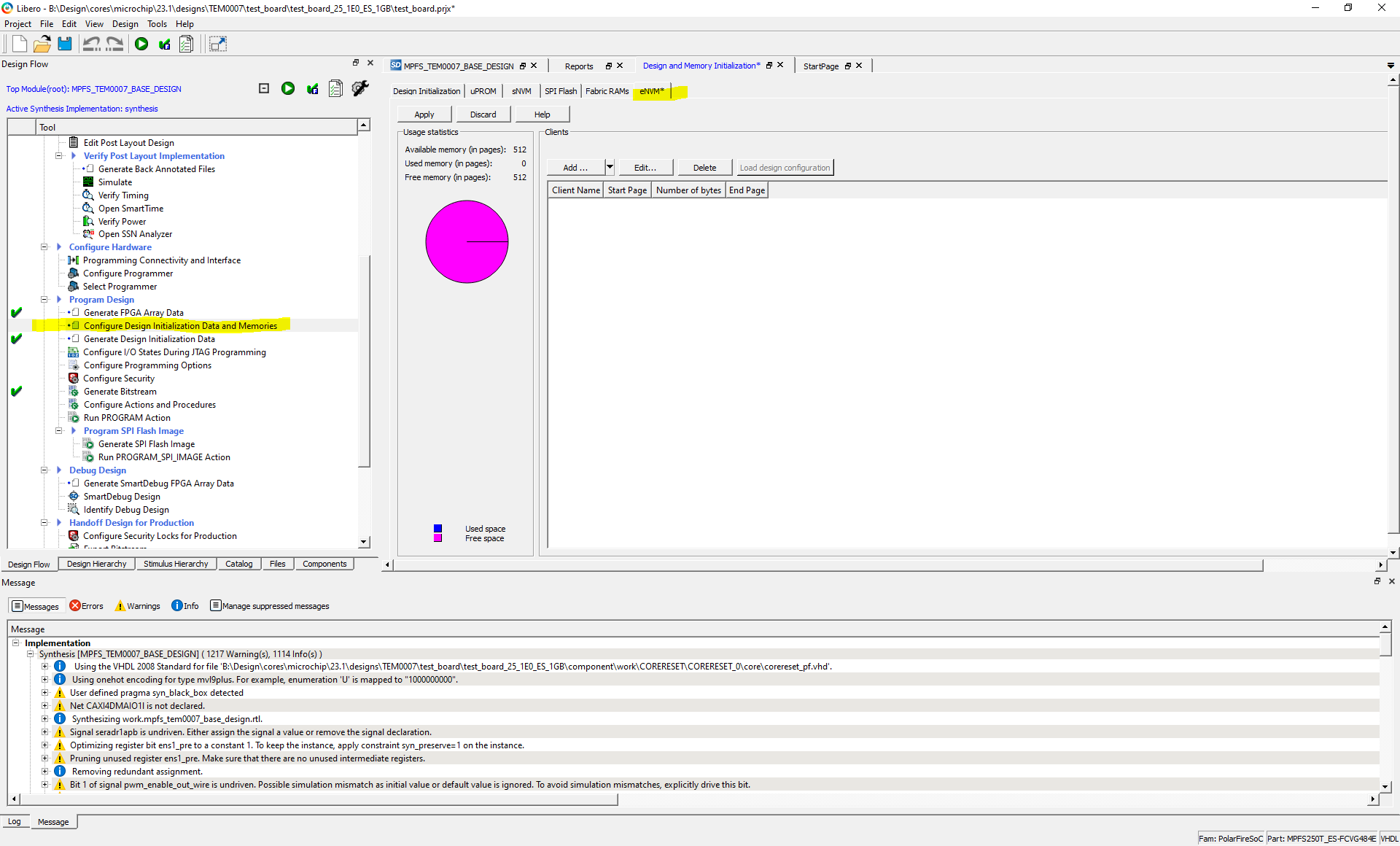 Image Added Image Added
|
- Click on eNVM and after that on Add and click on Add Boot Mode 1 Client.
- Enter the path of generated *.hex File by SoftConsole software (HSS) or the path of saved *.hex file in prebuilt folder ( for example "...\test_board\prebuilt\hardware\250_1E_1GB"and click on OK.
| Expand |
|---|
| title | HSS generated *.hex File attachment |
|---|
|
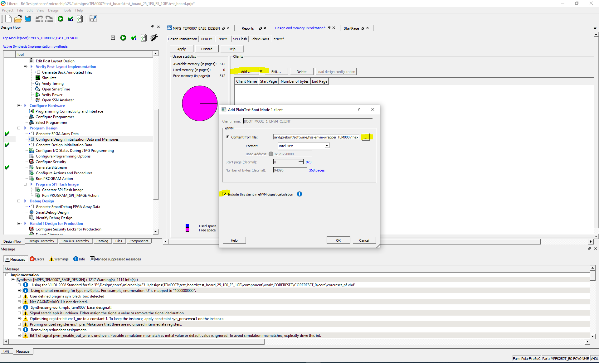 Image Added Image Added
|
- Save the project and double click on Generate Bitstream.
| Expand |
|---|
| title | Generate Bitstream again |
|---|
|
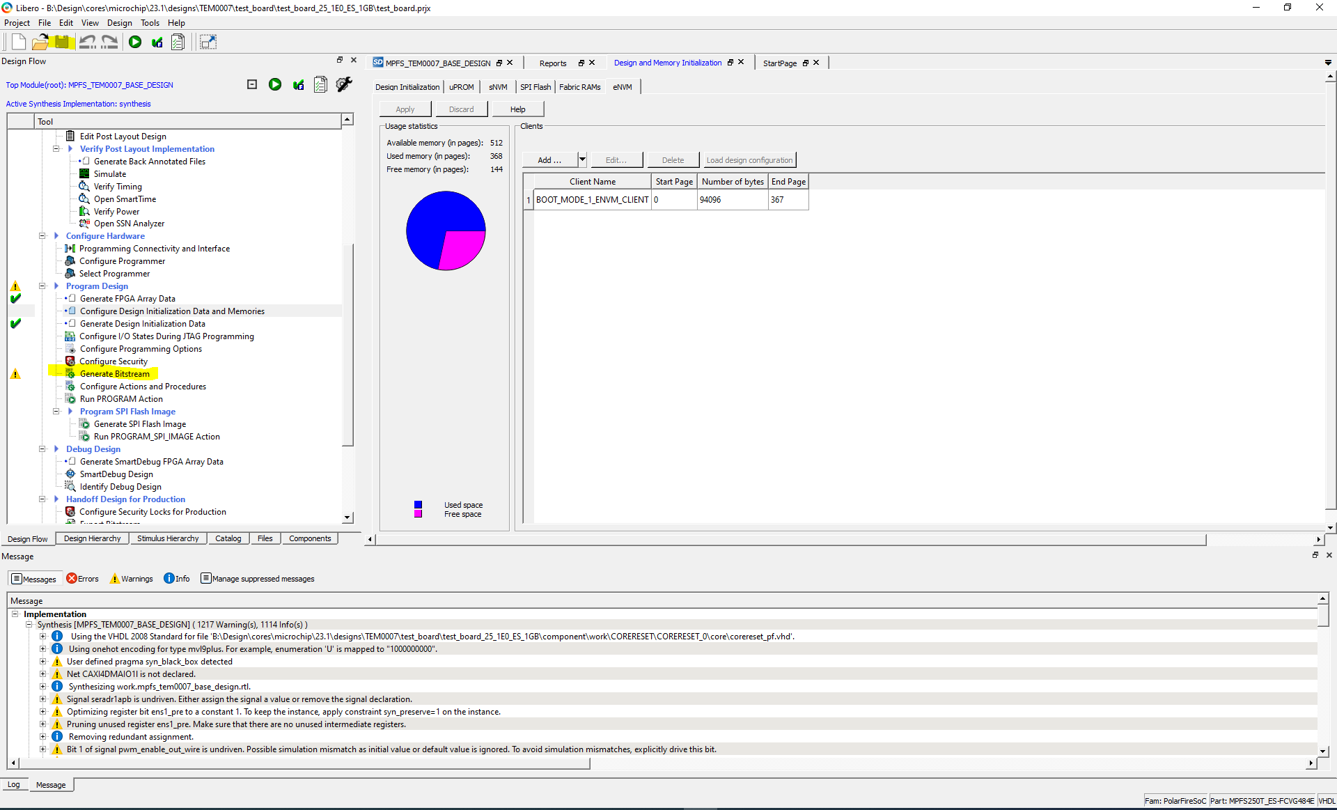 Image Added Image Added
|
- Double click on "Export Flashpro ExpressJob" and enter the desired path for *.job file to generate .job File. The *.job will be used to program the polarfire soc in FPExpress software.
| Expand |
|---|
|
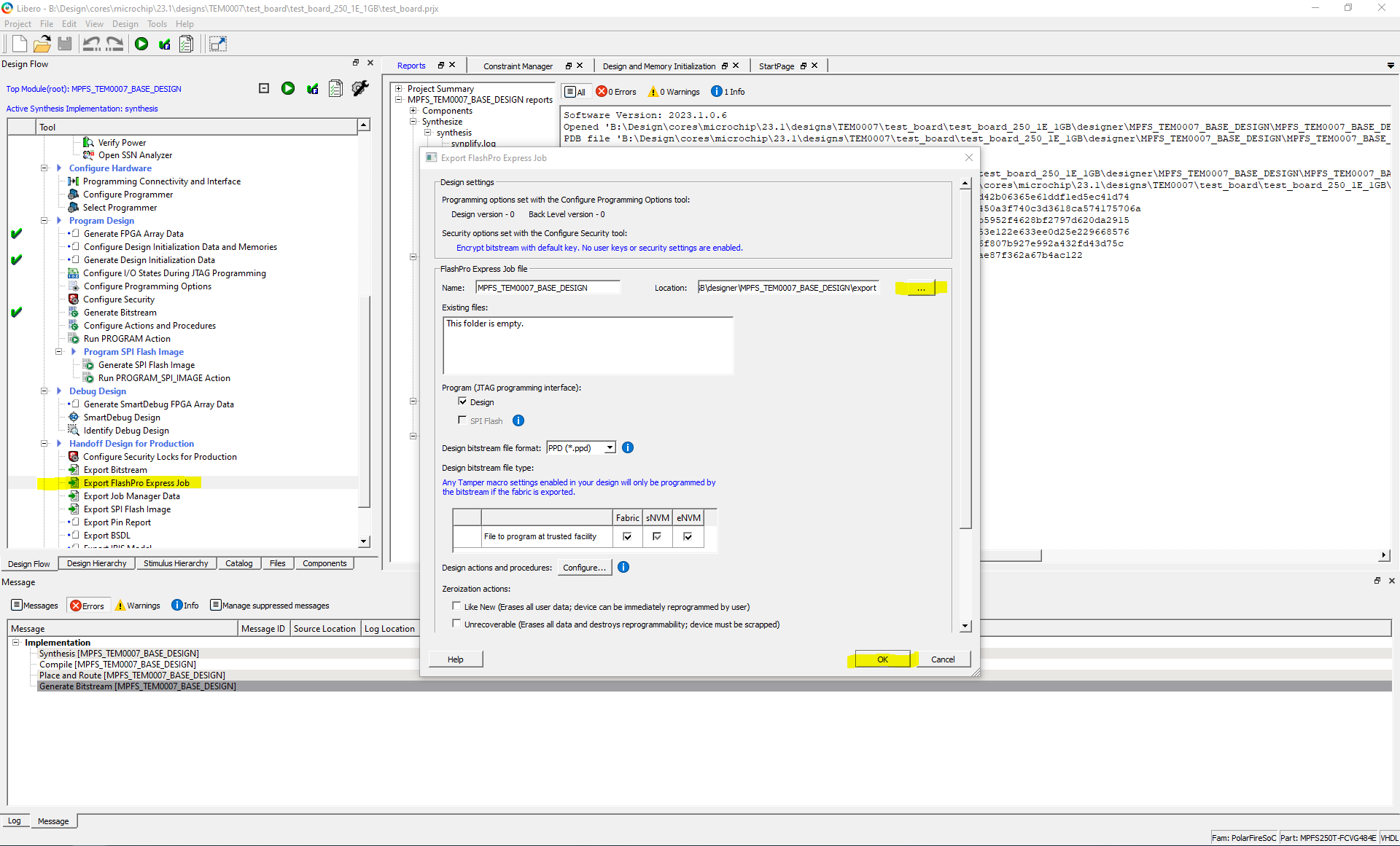 Image Added Image Added
|
Launch
| Page properties |
|---|
|
Get prebuilt boot binaries| Note |
|---|
Reference Design is also available with prebuilt files. It's recommended to use TE prebuilt files for first launch. |
|
Hardware Setup
| Page properties |
|---|
|
- Describe how to connect the carrier and board or only the board to the development PC .
- Programming and Startup procedure
|
- Connect the TEB2000 carrier board via its J4 mini USB connector to the PC. (For Linux console)
- Connect the TEB2000 carrier board via its J21 mini USB connector to the PC. (For HSS console)
- Connect the 5V power supply to 5V input voltage connector J13.
- Connect the RJ45 network cable to the ethernet interface J14.
- Connect the USB stick to the USB stick socket J12.
- For more information see TEB2000 Getting Started
Programming Bitstream
| Page properties |
|---|
|
| Describe how to programm the bitstream of the design onto the board or carrier . |
| Note |
|---|
Check module and carrier TRMs for proper HW configuration before you try any design. |
There is two ways to program bitstream file on FPGA. The Bitstream can be programmed into the FPGA / SOC by Libero SoC or Flash Pro Express :
Using Libero SoC
- Prepare the hardware see Hardware Setup
- Double click onto "Run PROGRAM Action" to program the Polarfire SoC.
| Expand |
|---|
| title | Programming FPGA using Libero SoC |
|---|
|
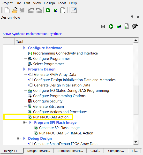 Image Added Image Added
|
Using FPExpress software
- Prepare the hardware see Hardware Setup
- Click on NEW... to open the "Creat New Job Project" dialog
- Clicking onto the upper Browse... button to specify the Programming Job File location
- Clicking onto the lower Browse... button to specify the location of where to store the FlashPro Express Job Project which will be created .The Job Project name automatically uses the programming job name and cannot be changed .
- Click OK and a new Job Project will be created and opened for production programming
- Click on RUN to start the programming of a board
| Expand |
|---|
| title | FPExpress software - Load .job-file and program board |
|---|
|
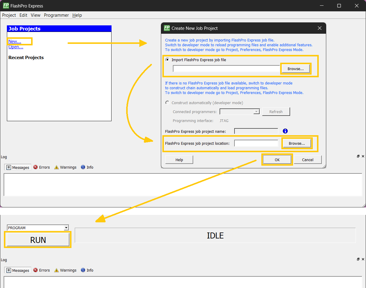 Image Added Image Added
|
Programming eNVM
| Page properties |
|---|
|
| Describe how to programm the bitstream of the design onto the board or carrier . |
The eNVM is a user non-volatile flash memory that can be programmed independently. There is two methods to program eNVM:
Programming eNVM in SoftConsole
To program HSS *.hex file on FPGA:
- Prepare the hardware see Hardware Setup
- Open SoftConsole software as administrator, if it is not done yet.
- Select correct directory as workspace directory and import hart-software-services source code.
- Right click on the hart-software-services and click on Build Project, if it is not done yet. For more information see Hart Software Services (HSS)
- Click on Run > External Tools > Polarfire SoC program non-secure boot-mode 1
Programming eNVM in Flashpro Express
The HSS generated hex file can be attached to bitstream file. For more information see Design Flow
To program the eNVM in Flashpro Express see Using FlashPro Express
| Page properties |
|---|
|
Get prebuilt boot binaries| Note |
|---|
Reference Design is also available with prebuilt files. It's recommended to use TE prebuilt files for first launch. |
|
SD-Boot mode
This module supports SD card boot and JTAG boot mode. The selection between them will be done in HSS, so there is no need to select the boot mode via Dip Switches .
Prepare SD card as follows for SD card boot mode:
- Extract SD_Card.zip file
- Now there is a image file (SD_Card.img)
- Alternative SD card can be written via win32diskimager or balenaEtcher softwares in Windows OS.
- In the case of writing image file in linux there are two commands to write image file on the SD card after mounting SD card in the host linux same as WSL:
| Expand |
|---|
|
| Code Block |
|---|
| theme | Midnight |
|---|
| linenumbers | true |
|---|
| bmaptool copy --nobmap <Path of image file *.img> /dev/sdX |
|
- After mounting the SD card in linux the name of SD card recognized via "lsblk" command. For example SD card name can be sda or sdb.
| Expand |
|---|
|
| Code Block |
|---|
| theme | Midnight |
|---|
| linenumbers | true |
|---|
| dd if=<Path of image file *.img> of=/dev/sdX |
|
- After mounting the SD card in linux the name of SD card recognized via lsblk command. For example SD card name can be sda or sdb.
JTAG
Not used on this example.
Usage
UART
- Open two serial console for HSS and Linux console (e.g. PuTTY)
Select COM Port of linux console (UART1)
| Info |
|---|
Win OS: see device manager Linux OS: see dmesg | grep tty (UART is *USB1) |
- Select COM port of HSS console (UART0)
- Speed for both consoles : 115200
- Press reset button
- Console output depends on used software project, see Application
- HSS console (UART0):
- This console can be monitored by user , to know some additional information same as SD card status ( If SD card by booting is detected or not) , U54 cores status or memory size , ....
| Expand |
|---|
|
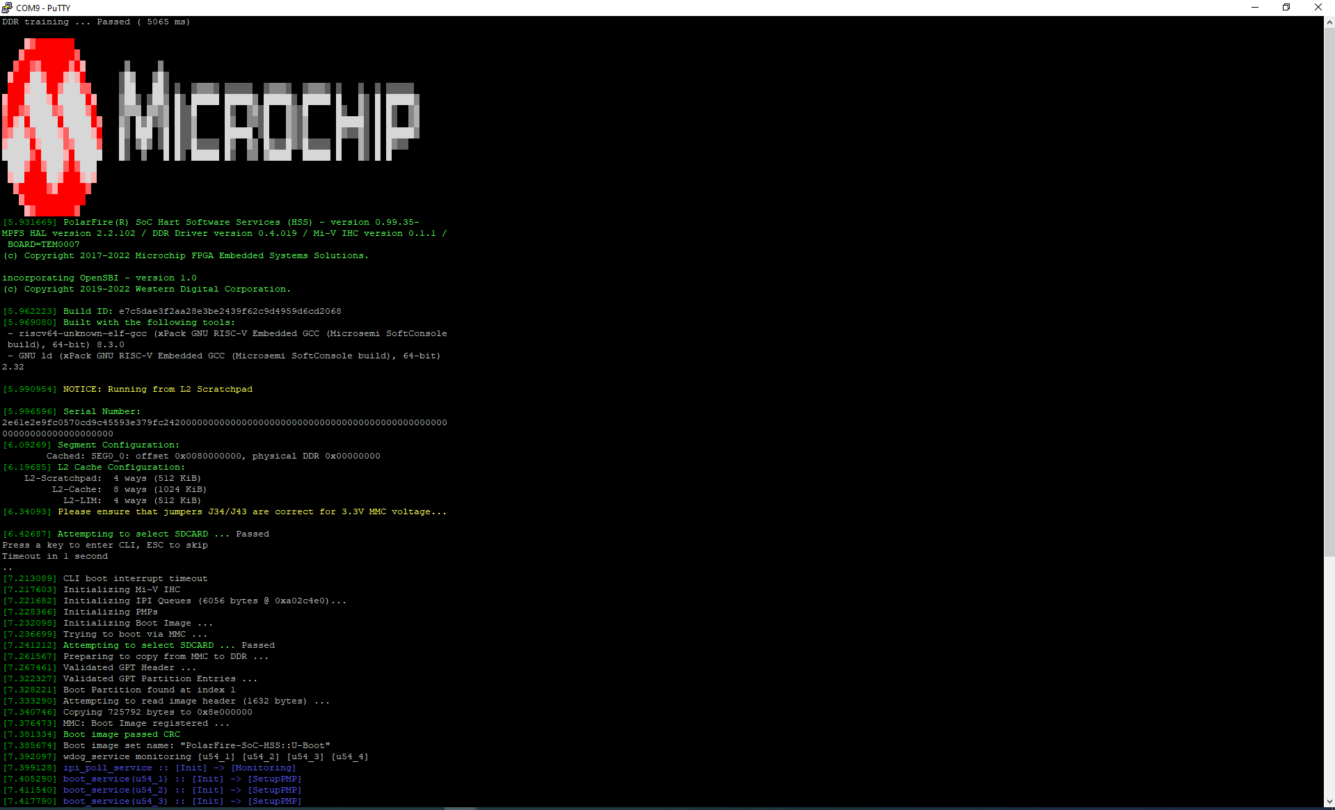 Image Added Image Added
|
- Linux Console (UART1):
Login data:
| Info |
|---|
Note: Wait until Linux boot finished |
| Code Block |
|---|
| theme | Midnight |
|---|
| linenumbers | true |
|---|
|
tem0007 login: root
|
You can use Linux shell now.
| Code Block |
|---|
| theme | Midnight |
|---|
| linenumbers | true |
|---|
|
i2cdetect -l        (check I2C Bus)
ifconfig -a         (ETH0 check)
lsusb (USB check) |
| Expand |
|---|
|
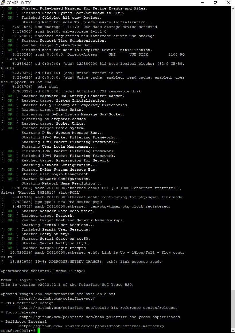 Image Added Image Added
|
System Design - Libero
Block Design
The Block Design of a board variant or revision may differ slightly depending on the assembly variant.
| Scroll Title |
|---|
| title-alignment | center |
|---|
| title | Block Design |
|---|
|
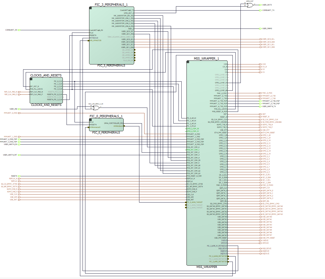 Image Added Image Added
|
HPS Interfaces
| Page properties |
|---|
|
List of active interfaces of the design . Please update the list |
Activated interfaces:
| Type | Note |
| DDR | -- |
| EMAC0 | -- |
| GPIO1 | -- |
| GPIO2 | -- |
| I2C0 | -- |
| I2C1 | -- |
SPI0
| --
|
| QSPI | -- |
| SDMMC | -- |
| UART0 | -- |
| UART1 | -- |
| USB | -- |
Constraints
| Page properties |
|---|
|
Insert all constraint files which the Hardware Design uses here . If a division into sub chapters is necessary , the subchapters "Basic module constrains" and "Design specific constrain" have been added . Delete them not necessary . |
| Code Block |
|---|
| title | TEM0007_Bank_Voltage.pdc |
|---|
|
set_iobank -bank_name Bank0  \
    -vcci 1.80               \
    -fixed true             \
    -update_iostd true

set_iobank -bank_name Bank1  \
    -vcci 3.30               \
    -fixed true             \
    -update_iostd true

set_iobank -bank_name Bank4  \
    -vcci 3.30               \
    -fixed true             \
    -update_iostd true
|
| Code Block |
|---|
|
set_io -port_name REF_CLK_PAD_P  \
    -pin_name J19                \
    -DIRECTION INPUT

set_io -port_name REF_CLK_PAD_N  \
    -pin_name J20                \
-DIRECTION INPUT |
| Code Block |
|---|
|
set_io -port_name GPIO_2_2  \
    -pin_name D9              \
    -fixed true               \
    -io_std LVCMOS33          \
    -DIRECTION INOUT

set_io -port_name GPIO_2_3  \
    -pin_name D6              \
    -fixed true               \
    -io_std LVCMOS33          \
    -DIRECTION INOUT

set_io -port_name GPIO_2_4  \
    -pin_name C6              \
    -fixed true               \
    -io_std LVCMOS33          \
    -DIRECTION INOUT

set_io -port_name GPIO_2_7  \
    -pin_name B5              \
    -fixed true               \
    -io_std LVCMOS33          \
    -DIRECTION INOUT

set_io -port_name GPIO_2_8  \
    -pin_name C5              \
    -fixed true               \
    -io_std LVCMOS33          \
    -DIRECTION INOUT

set_io -port_name GPIO_2_9  \
    -pin_name C4              \
    -fixed true               \
    -io_std LVCMOS33          \
    -DIRECTION INOUT

set_io -port_name GPIO_2_11  \
    -pin_name F16             \
    -fixed true               \
    -io_std LVCMOS33          \
    -DIRECTION INOUT

set_io -port_name GPIO_2_12  \
    -pin_name D14             \
    -fixed true               \
    -io_std LVCMOS33          \
    -DIRECTION INOUT

set_io -port_name GPIO_2_13  \
    -pin_name E14             \
    -fixed true               \
    -io_std LVCMOS33          \
    -DIRECTION INOUT

set_io -port_name GPIO_2_14  \
    -pin_name B4              \
    -fixed true               \
    -io_std LVCMOS33          \
-DIRECTION INOUT |
| Code Block |
|---|
|
set_io -port_name MAC_0_MDC \
    -pin_name H6 \
    -fixed true \
    -DIRECTION OUTPUT \
    -io_std LVCMOS33

set_io -port_name MAC_0_MDIO \
    -pin_name J3 \
    -fixed true \
    -DIRECTION INOUT \
    -io_std LVCMOS33
|
| Code Block |
|---|
|
 set_io -port_name MMUART_0_TXD \
    -pin_name C2 \
    -fixed true \
    -DIRECTION OUTPUT \
    -io_std LVCMOS33

set_io -port_name MMUART_0_RXD \
    -pin_name D3 \
    -fixed true \
    -DIRECTION INPUT \
-io_std LVCMOS33 |
| Code Block |
|---|
|
set_io -port_name MMUART_1_TXD \
    -pin_name H5 \
    -fixed true \
    -DIRECTION OUTPUT \
    -io_std LVCMOS33

set_io -port_name MMUART_1_RXD \
    -pin_name H2 \
    -fixed true \
    -DIRECTION INPUT \
-io_std LVCMOS33 |
| Code Block |
|---|
| title | TEM0007_Peripheral.pdc |
|---|
|
set_io -port_name USER_PWM0    \
    -pin_name D7    \
    -fixed true    \
    -io_std LVCMOS33  \
    -RES_PULL Down \
    -DIRECTION OUTPUT

set_io -port_name USER_IN0 \
    -pin_name V19 \
    -fixed true \
    -DIRECTION INPUT

set_io -port_name USER_OUT0 \
    -pin_name AB19 \
    -fixed true \
    -DIRECTION OUTPUT

# JM2-Pin73/ JB2-Pin74 / B13_L16_N (Suitable for modified TE0703)
#set_io -port_name RESETN  \
    -pin_name H13         \
    -fixed true           \
    -io_std LVTTL         \
    -CLAMP_DIODE OFF      \
    -RES_PULL Up          \
    -DIRECTION INPUT

# JM2-Pin55 TEM0007 / JB2-Pin56 (SRST) TEB2000 / B13_L9_P
set_io -port_name RESETN  \
    -pin_name E15         \
    -fixed true           \
    -io_std LVTTL         \
    -CLAMP_DIODE OFF      \
    -RES_PULL Up          \
    -DIRECTION INPUT
|
| Code Block |
|---|
|
set_io -port_name QSPI_CLK  \
    -pin_name C10           \
    -fixed true             \
    -io_std LVCMOS33        \
    -DIRECTION INOUT

set_io -port_name QSPI_DATA_0  \
    -pin_name D13              \
    -fixed true                \
    -io_std LVCMOS33           \
    -DIRECTION INOUT

set_io -port_name QSPI_DATA_1  \
    -pin_name B12              \
    -fixed true                \
    -io_std LVCMOS33           \
    -DIRECTION INOUT

set_io -port_name QSPI_DATA_2  \
    -pin_name C9               \
    -fixed true                \
    -io_std LVCMOS33           \
    -DIRECTION INOUT

set_io -port_name QSPI_DATA_3  \
    -pin_name C12              \
    -fixed true                \
    -io_std LVCMOS33           \
    -DIRECTION INOUT

set_io -port_name QSPI_SEL  \
    -pin_name A13           \
    -fixed true             \
    -io_std LVCMOS33        \
-DIRECTION INOUT |
| Code Block |
|---|
| title | MPFS_TEM0007_BASE_DESIGN_derived_constraints.sdc |
|---|
|
create_generated_clock -name {CLOCKS_AND_RESETS_inst_0/CCC_FIC_x_CLK/PF_CCC_C0_0/pll_inst_0/OUT0} -multiply_by 5 -source [ get_pins { CLOCKS_AND_RESETS_inst_0/CCC_FIC_x_CLK/PF_CCC_C0_0/pll_inst_0/REF_CLK_0 } ] -phase 0 [ get_pins { CLOCKS_AND_RESETS_inst_0/CCC_FIC_x_CLK/PF_CCC_C0_0/pll_inst_0/OUT0 } ]
create_generated_clock -name {CLOCKS_AND_RESETS_inst_0/CCC_FIC_x_CLK/PF_CCC_C0_0/pll_inst_0/OUT1} -multiply_by 5 -source [ get_pins { CLOCKS_AND_RESETS_inst_0/CCC_FIC_x_CLK/PF_CCC_C0_0/pll_inst_0/REF_CLK_0 } ] -phase 0 [ get_pins { CLOCKS_AND_RESETS_inst_0/CCC_FIC_x_CLK/PF_CCC_C0_0/pll_inst_0/OUT1 } ]
create_generated_clock -name {CLOCKS_AND_RESETS_inst_0/CCC_FIC_x_CLK/PF_CCC_C0_0/pll_inst_0/OUT2} -multiply_by 5 -source [ get_pins { CLOCKS_AND_RESETS_inst_0/CCC_FIC_x_CLK/PF_CCC_C0_0/pll_inst_0/REF_CLK_0 } ] -phase 0 [ get_pins { CLOCKS_AND_RESETS_inst_0/CCC_FIC_x_CLK/PF_CCC_C0_0/pll_inst_0/OUT2 } ]
create_generated_clock -name {CLOCKS_AND_RESETS_inst_0/CCC_FIC_x_CLK/PF_CCC_C0_0/pll_inst_0/OUT3} -multiply_by 2 -source [ get_pins { CLOCKS_AND_RESETS_inst_0/CCC_FIC_x_CLK/PF_CCC_C0_0/pll_inst_0/REF_CLK_0 } ] -phase 0 [ get_pins { CLOCKS_AND_RESETS_inst_0/CCC_FIC_x_CLK/PF_CCC_C0_0/pll_inst_0/OUT3 } ]
create_generated_clock -name {CLOCKS_AND_RESETS_inst_0/PF_CLK_DIV_C1_0/PF_CLK_DIV_C1_0/I_CD/Y_DIV} -edges {1 7 11} -source [ get_pins { CLOCKS_AND_RESETS_inst_0/PF_CLK_DIV_C1_0/PF_CLK_DIV_C1_0/I_CD/A } ] [ get_pins { CLOCKS_AND_RESETS_inst_0/PF_CLK_DIV_C1_0/PF_CLK_DIV_C1_0/I_CD/Y_DIV } ]
set_false_path -through [ get_nets { FIC_0_PERIPHERALS_1/DMA_INITIATOR_inst_0/ARESETN* } ]
set_false_path -through [ get_nets { FIC_0_PERIPHERALS_1/FIC0_INITIATOR_inst_0/ARESETN* } ]
|
Software Design - SoftConsole
| Page properties |
|---|
|
Describe How to generate / compile the application . Use sections for different applications . E.g. :
Create a project / the specific required project type in Softconsole , integrate the sources from the Trenz Board Download , setup the build chain and configure Debug and Compile Profiles . |
Application
| Page properties |
|---|
|
---------------------------------------------------------- General Example: |
Template location: <project folder>/softconsole_source/
Hart Software Services (HSS)
Hart Software Services (HSS) code on PolarFire SoC, is comprised of two portions:
A superloop monitor running on the E51 minion processor, which receives requests from the individual U54 application processors to perform certain services on their behalf.
A Machine-Mode software interrupt trap handler, which allows the E51 to send messages to the U54s, and request them to perform certain functions for it related to rebooting a U54.
The HSS performs boot and system monitoring functions for PolarFire SoC. The HSS is compressed (DEFLATE) and stored in eNVM. On power-up, a small decompressor wrapper inflates the HSS from eNVM flash to L2-Scratchpad memory and starts the HSS.
Creating HSS workspace in SoftConsole
- Download the test board design zip file in the following path : TEM0007 "Test Board" Reference Design
- Unzip the test board zip file
- Copy the HSS folder (hart-software-services-<HSS version>) from softconsole_source folder in the SoftConsole workspace folder
- Open SoftConsole software as administrator
- Select correct directory as workspace directory. The workspace folder must consist of hart-software-services-<HSS version> folder. The hart-software-services-<HSS version> project can be imported in the workspace as an Existing project.
- Left click on board folder
- There is created already a subfolder for TEM0007 module and HSS is ready to be compiled as shown:
| Expand |
|---|
|
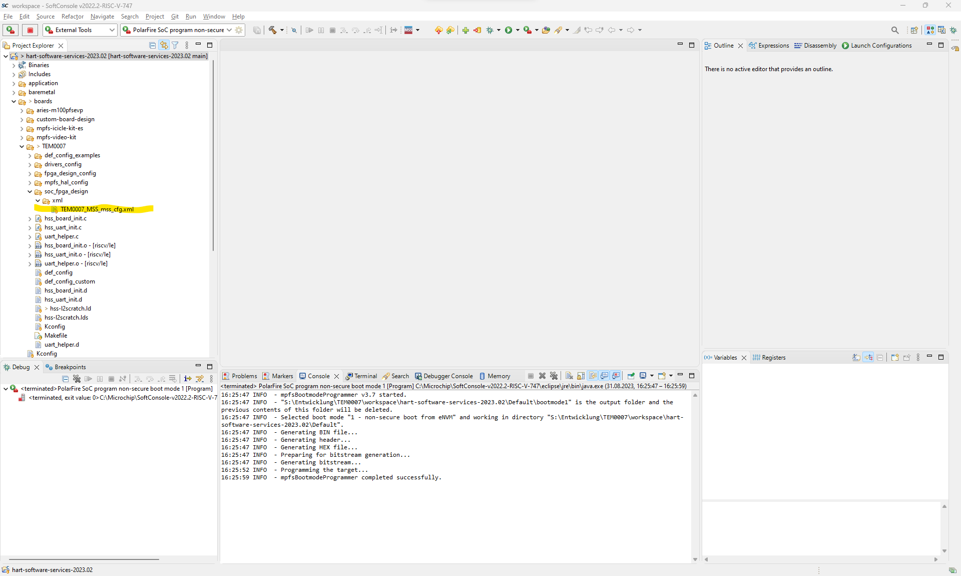 Image Added Image Added
|
- Right click on hart-software-services-<HSS version> and click on Build project to compile it.
- It is ready to program created hex file on the Polarfire SoC. See Programming eNVM
Note that HSS can be changed for every TEM0007 variant. Therefore the hex file for every variant is created and saved in the following path of test design folder separately: (<project folder>/prebuilt/soctware/<short name of the module variant>)
Creating XML file in PolarfireSoC MSS Configurator Software
To create HSS file for a desired module variant the saved MSS configuration xml file in "<softconsole workspace folder>/ hart-software-services-<HSS version>/board/TEM0007/soc_fpgs_design/xml/" must be matched for its related xml file. To do it:
- Open the PolarfireSoC MSS Configurator software.
- Click on Project→Open
- Select the generated TEM0007_MSS.cfg file that is saved in the "<project folder>/prebuilt/mss/<short name of the module variant>" folder.
- Click on Generate icon. It will be opened a window to enter the desired path for generated xml file.
| Expand |
|---|
|
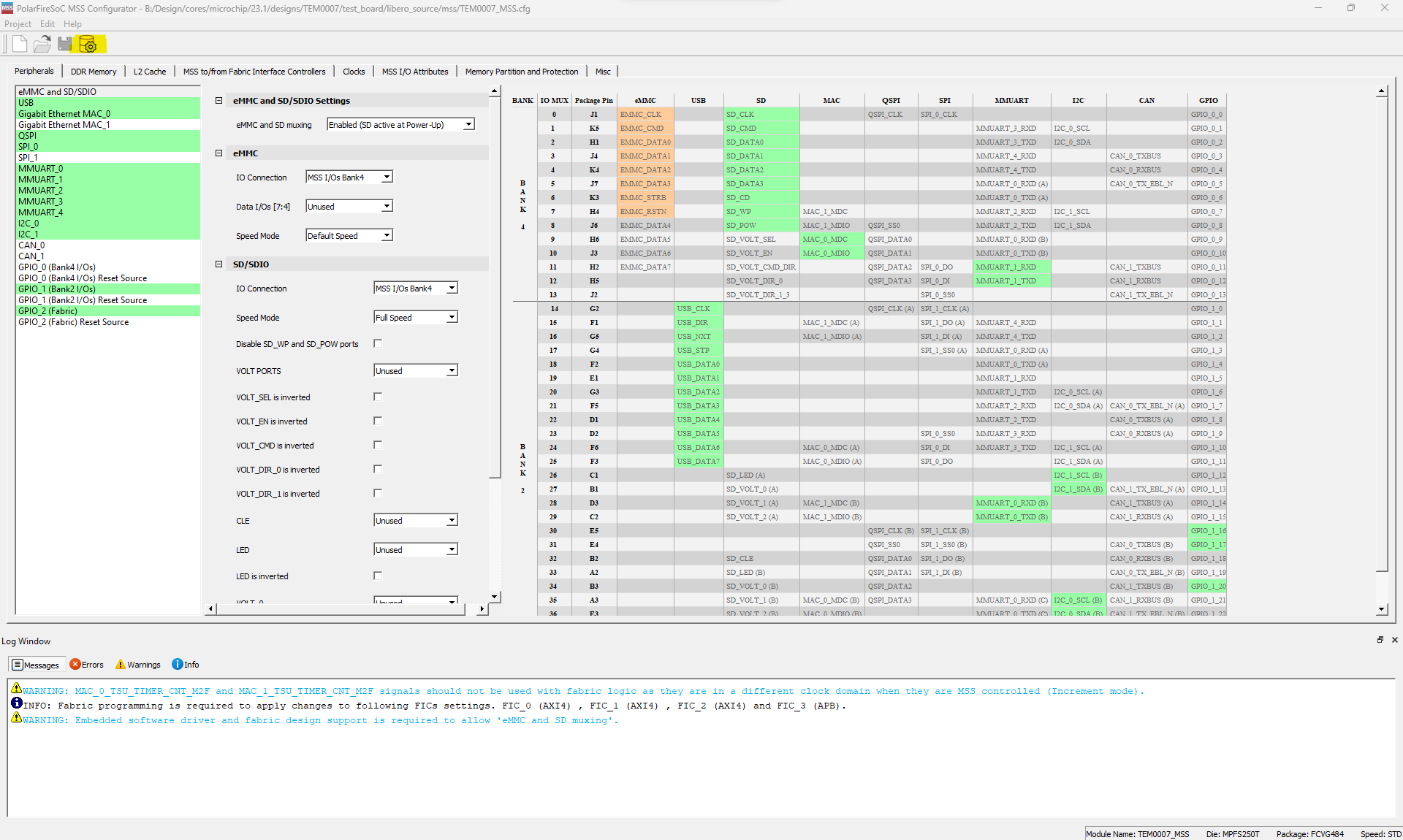 Image Added Image Added
|
- MSS configuration xml file is generated. This file must be imported in SoftConsole software. To import this file copy the generated MSS configuration xml file and replace it with previous xml file in the following path : "<softconsole workspace folder>/ hart-software-services-<HSS version>/boards/TEM0007/soc_fpga_design/xml"
- Right click on the project in SoftConsole software and click on Clean Project.
- In SoftConsole software delete all configuration header files in "<softconsole workspace folder>/ hart-software-services-<HSS version>/boards/TEM0007/fpga_design-config"folder.
| Expand |
|---|
| title | Delete configuration header files |
|---|
|
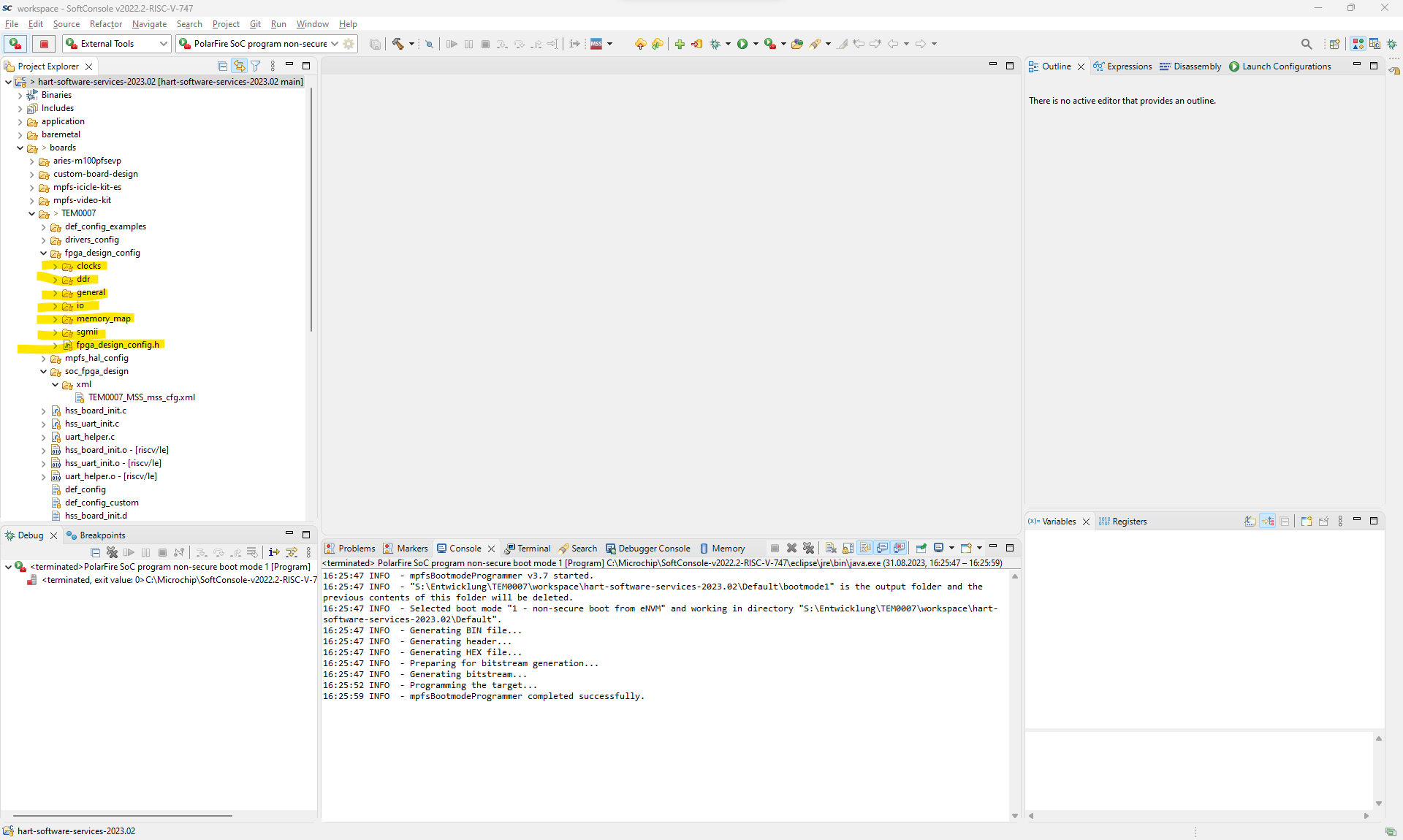 Image Added Image Added
|
- Right click on the project in SoftConsole software again and click on Build Project to compile the project.
- The new configuration header files will be generated again by the python script in "<softconsole workspace folder>/ hart-software-services-<HSS version>/tools/polarfire-soc-configuration-generator/mpfs_configuration_generator.py "folder. The generated hex file can be found in the "<softconsole workspace folder>/ hart-software-services-<HSS version>/Default " folder.
- This new hex file must be replaced in Libero to generate new Bitstream file, if this hex file should be attached in Bitstream file. See Libero SoC
Note that this hex file can be programmed in eNVM in SoftConsole directly. See Programming eNVM in SoftConsole
Software Design - Yocto
| Page properties |
|---|
|
Describe how to generate / compile the Linux distribution . E.g. :
Software Requirements for the Compiling OS , obtaining the sources and adding the sources from the Trenz Board Download , running the compilation script . |
The host pc must be prepared for using the yocto. For more information about host pc setup for yocto and the required packets please refer to System Requirements
Trenz electronic has developed his own BSP for Microchip devices same as polarfire soc in Yocto. In the following will be explained the folders in detail.
| meta-trenz-polarfire-bsp Folder | Description |
|---|
| recipes-apps* | Consists of start up application for executing of init.sh by booting. More application can be saved in this folder.
|
|---|
| recipes-bsp | Consists of uboot required files same as *.bbappend files, device tree and etc. |
|---|
| recipes-core | Consists of *.bb file for Trenz defined image version. This file consists of required packets or files that must be installed.
|
|---|
| recipes-kernel | Consists of kernel required files same as *.bbappend files, device tree, config files and etc. |
|---|
| recipes-tools | Consists of a *.bbappend file. |
|---|
| tools | Consists of manifest xml file to define meta data that are required. |
|---|
| wic | Consists of *.wks file that describes disk image properties.
|
|---|
*Note: In this version is not used.
In the following table exists more information about required packets and supported version.
| Meta data | Supported Version | Description |
|---|
| meta-riscv | Kirkstone |
|
|---|
| openembedded-core | Kirkstone |
|
|---|
| meta-openembedded | Kirkstone |
|
|---|
| meta-polarfire-soc-yocto-bsp | 2022.11 |
|
|---|
Trenz BSP contains of a shell script. If this shell script is executed , all required processes for making a linux image file will be executed automatically. The user needs only to write the generated image file on the SD card. To prepare the image file :
- Create a new folder (for example TEM0007) in host linux ( here Ubuntu18.04 and Ubuntu 20.04 have been tested )
- Download the test board design as zip file (See Download) and save meta-trenz-polarefile-bsp BSP folder from "<project folder>/os/yocto/ " folder in the created folder. (for example TEM0007)
- Go to the created folder (for example TEM0007) that meta-trenz-polarfire-bsp is saved and execute its shell script as shown:
| Expand |
|---|
| title | Execute shell script |
|---|
|
| Code Block |
|---|
| theme | Midnight |
|---|
| linenumbers | true |
|---|
| . ./meta-trenz-polarfire-bsp/trenz_polarfire_setup.sh |
|
*Note: The shell script must be executed in created new folder (for example TEM0007) that has bsp folder saved in it. - After compiling image file *.img and its converted zip file *.zip will be saved in trenz bsp folder:
U-Boot
| Page properties |
|---|
|
Please update the listing of ... . |
File location: <trenz BSP folder>/recipes-bsp/u-boot/
Changes:
CONFIG_PHY_MARVELL=y
CONFIG_DEFAULT_DEVICE_TREE="tem0007"
CONFIG_DEFAULT_FDT_FILE="tem0007.dtb"
CONFIG_OF_LIST="tem0007"
CONFIG_DM_GPIO=y
CONFIG_CMD_GPIO=y
CONFIG_LOG=y
CONFIG_LOG_MAX_LEVEL=y
CONFIG_LOG_CONSOLE=y
CONFIG_NVMEM=y → to be able to read MAC vom EEPROM
CONFIG_DM_RTC=y
Device Tree
| Page properties |
|---|
|
Please insert the Device Tree files into the Codeblocks below . Add or remove Codeblocks if necessary |
U-boot Device Tree
| Code Block |
|---|
| language | js |
|---|
| title | tem0007.dtsi |
|---|
|
// SPDX-License-Identifier: (GPL-2.0 OR MIT)
/*
 * Copyright (C) 2020 Microchip Technology Inc.
 * Padmarao Begari <padmarao.begari@microchip.com>
 */

/ {
	aliases {
		cpu1 = &cpu1;
		cpu2 = &cpu2;
		cpu3 = &cpu3;
		cpu4 = &cpu4;
	};
}; |
| Code Block |
|---|
|
// SPDX-License-Identifier: (GPL-2.0+ OR MIT)
/*
* Copyright (C) 2021 Microchip Technology Inc.
* Padmarao Begari <padmarao.begari@microchip.com>
*/
/dts-v1/;
#include "microchip-mpfs.dtsi"
#include "dt-bindings/gpio/gpio.h"
/* Clock frequency (in Hz) of the rtcclk */
#define RTCCLK_FREQ 1000000
/ {
model = "Microchip PolarFire-SoC Icicle Kit";
compatible = "microchip,mpfs-icicle-kit", "microchip,mpfs";
aliases {
serial1 = &uart1;
ethernet0 = &mac0;
spi0 = &qspi;
};
chosen {
stdout-path = "serial1";
};
cpus {
timebase-frequency = <RTCCLK_FREQ>;
};
ddrc_cache: memory@80000000 {
device_type = "memory";
reg = <0x0 0x80000000 0x0 0x40000000>;
clocks = <&clkcfg CLK_DDRC>;
status = "okay";
};
usb_phy: usb_phy {
#phy-cells = <0>;
compatible = "usb-nop-xceiv";
reset-gpios = <&gpio1 17 GPIO_ACTIVE_LOW>;
reset-names = "OTG_RST";
};
};
&uart1 {
status = "okay";
};
&mmc {
status = "okay";
bus-width = <4>;
disable-wp;
cap-mmc-highspeed;
cap-sd-highspeed;
cd-debounce-delay-ms;
card-detect-delay = <200>;
// mmc-ddr-1_8v;
// mmc-hs200-1_8v;
sd-uhs-sdr12;
sd-uhs-sdr25;
sd-uhs-sdr50;
sd-uhs-sdr104;
};
&i2c1 {
status = "okay";
#address-cells = <1>;
#size-cells = <0>;
eeprom: eeprom@50 {
compatible = "microchip,24aa025", "atmel,24c02";
//compatible = "atmel,24c02";
reg = <0x50>;
#address-cells = <1>;
#size-cells = <1>;
eth0_addr: eth-mac-addr@FA {
reg = <0xFA 0x06>;
};
};
};
&refclk {
clock-frequency = <125000000>;
};
&mac1 {
status = "disabled";
};
&mac0 {
status = "okay";
phy-mode = "sgmii";
nvmem-cells = <ð0_addr>;
nvmem-cell-names = "mac-address";
phy-handle = <&phy0>;
phy0: ethernet-phy@1 {
device-type = "ethernet-phy";
reg = <1>;
reset-names = "ETH_RST";
reset-gpios = <&gpio1 16 GPIO_ACTIVE_LOW>;
};
};
&qspi {
status = "okay";
num-cs = <1>;
flash0: spi-nor@0 {
compatible = "spi-nor";
reg = <0x0>;
spi-tx-bus-width = <4>;
spi-rx-bus-width = <4>;
spi-max-frequency = <20000000>;
spi-cpol;
spi-cpha;
};
};
&usb {
status = "okay";
dr_mode = "otg";
// dr_mode = "host";
phys = <&usb_phy>;
};
|
Kernel Device Tree
| Code Block |
|---|
| language | js |
|---|
| title | tem0007.dts |
|---|
|
// SPDX-License-Identifier: (GPL-2.0 OR MIT)
/* Copyright (c) 2020-2021 Microchip Technology Inc */
/dts-v1/;
#include "mpfs.dtsi"
#include <dt-bindings/gpio/gpio.h>
#include <dt-bindings/phy/phy.h>
/* Clock frequency (in Hz) of the rtcclk */
#define MTIMER_FREQ 1000000
/ {
#address-cells = <2>;
#size-cells = <2>;
model = "Trenz TEM0007";
compatible = "trenz,tem0007","microchip,mpfs";
aliases {
ethernet0 = &mac0;
serial0 = &mmuart0;
serial1 = &mmuart1;
serial2 = &mmuart2;
serial3 = &mmuart3;
serial4 = &mmuart4;
};
chosen {
stdout-path = "serial1:115200n8";
};
cpus {
timebase-frequency = <MTIMER_FREQ>;
};
//******************************************************//
ddrc_cache: memory@80000000 {
device_type = "memory";
reg = <0x0 0x80000000 0x0 0x40000000>;
status = "okay";
};
reserved-memory {
#address-cells = <2>;
#size-cells = <2>;
ranges;
fabricbuf0ddrc: buffer@A0000000 {
compatible = "shared-dma-pool";
reg = <0x0 0xA0000000 0x0 0x2000000>;
no-map;
};
};
udmabuf0 {
compatible = "ikwzm,u-dma-buf";
device-name = "udmabuf-ddr-c0";
minor-number = <0>;
size = <0x0 0x2000000>;
memory-region = <&fabricbuf0ddrc>;
sync-mode = <3>;
};
//******************************************************//
usb_phy: usb_phy {
#phy-cells = <0>;
compatible = "usb-nop-xceiv";
reset-gpios = <&gpio1 17 GPIO_ACTIVE_LOW>;
reset-names = "OTG_RST";
};
soc {
dma-ranges = <0 0 0 0 0x40 0>;
};
};
&gpio1 {
status = "okay";
};
&gpio2 {
interrupts = <53>, <53>, <53>, <53>,
<53>, <53>, <53>, <53>,
<53>, <53>, <53>, <53>,
<53>, <53>, <53>, <53>,
<53>, <53>, <53>, <53>,
<53>, <53>, <53>, <53>,
<53>, <53>, <53>, <53>,
<53>, <53>, <53>, <53>;
status = "okay";
};
&i2c0 {
status = "okay";
};
&i2c1 {
status = "okay";
#address-cells = <1>;
#size-cells = <0>;
eeprom: eeprom@50 {
compatible = "microchip,24aa025", "atmel,24c02";
//compatible = "atmel,24c02";
reg = <0x50>;
#address-cells = <1>;
#size-cells = <1>;
eth0_addr: eth-mac-addr@FA {
reg = <0xFA 0x06>;
};
};
};
&mac0 {
status = "okay";
phy-mode = "sgmii";
nvmem-cells = <ð0_addr>;
nvmem-cell-names = "mac-address";
phy-handle = <&phy0>;
phy0: ethernet-phy@1 {
device-type = "ethernet-phy";
reg = <1>;
reset-names = "ETH_RST";
reset-gpios = <&gpio1 16 GPIO_ACTIVE_LOW>;
};
};
&mbox {
status = "okay";
};
&mmc {
status = "okay";
bus-width = <4>;
disable-wp;
cap-sd-highspeed;
cap-mmc-highspeed;
// mmc-ddr-1_8v;
// mmc-hs200-1_8v;
sd-uhs-sdr12;
sd-uhs-sdr25;
sd-uhs-sdr50;
sd-uhs-sdr104;
};
&mmuart1 {
status = "okay";
};
&mmuart2 {
status = "okay";
};
&mmuart3 {
status = "okay";
};
&mmuart4 {
status = "okay";
};
&qspi {
status = "okay";
num-cs = <1>;
};
&refclk {
clock-frequency = <125000000>;
};
&spi0 {
status = "okay";
};
&usb {
status = "okay";
dr_mode = "otg";
// dr_mode = "host";
phys = <&usb_phy>;
};
&syscontroller {
status = "okay";
};
|
Kernel
| Page properties |
|---|
|
Please update the listing of ... . |
File location: <trenz BSP folder>/recipes-kernel/linux/
Changes:
CONFIG_CMDLINE_BOOL=y
CONFIG_CMDLINE="earlycon=sbi root=/dev/mmcblk0p3 rootwait uio_pdrv_genirq.of_id=generic-uio"
CONFIG_EEPROM_AT24=y
CONFIG_NVMEM=y
CONFIG_NVMEM_SYS=y
CONFIG_REGMAP_I2C=y
- CONFIG_MARVELL_PHY=y
CONFIG_LEDS_GPIO=y
CONFIG_LEDS_CLASS=y
CONFIG_NEW_LEDS=y
CONFIG_GPIOLIB=y
CONFIG_USB_MUSB_HOST=y
CONFIG_USB_MUSB_DUAL_ROLE=y
CONFIG_MTD_SPI_NOR_USE_4K_SECTORS=n
CONFIG_MTD_UBI=y
CONFIG_MTD_CMDLINE_PARTS=y
CONFIG_UBIFS_FS=y
CONFIG_MTD_SPI_NOR=y
CONFIG_OF_OVERLAY=y
CONFIG_OF_CONFIGFS=y
CONFIG_MFD_SENSEHAT_CORE=m
CONFIG_INPUT_JOYDEV=m
CONFIG_INPUT_JOYSTICK=y
CONFIG_JOYSTICK_SENSEHAT=m
CONFIG_AUXDISPLAY=y
CONFIG_SENSEHAT_DISPLAY=m
CONFIG_HTS221=m
CONFIG_IIO_ST_PRESS=m
CONFIG_IIO_ST_LSM6DSX=m
CONFIG_IIO_ST_MAGN_3AXIS=m
#CONFIG_MUSB_PIO_ONLY is not set
CONFIG_USB_INVENTRA_DMA=y
Images
| Page properties |
|---|
|
Please update the listing of ... . |
Image recipe for minimal console image
File location: <trenz BSP folder>/recipes-core/images/
Image recipes:
- te-image-minimal.bb: create minimal linux image
Added packages/recipes:
Rootfs
| Page properties |
|---|
|
Please update the listing of ... . |
Used filesystem: Root file system (RootFS
Build the image with following command (the image recipes are located in meta-<module>/recipes-core/images/):
| Code Block |
|---|
| theme | Midnight |
|---|
| linenumbers | true |
|---|
|
bitbake te-image-minimal |
Launch
| Scroll Ignore |
|---|
| Page properties |
|---|
|
Note: - Programming and Startup procedure
|
Programming
| Note |
|---|
Check Module and Carrier TRMs for proper HW configuration before you try any design. |
Get prebuilt boot binaries
| Note |
|---|
Reference Design is also available with prebuilt files. It's recommended to use TE prebuilt files for first launch. |
- Run create_project_win.cmd/create_project_linux.sh
- Select Module in 'Board selection'
- Click on 'Export prebuilt files' button
- Folder <project folder>/_binaries_<Article Name> with subfolder boot_linux will be generated and opened
SD-Boot mode
Prepare SD card as follows for SD-BootRun following command to get the device name of the SD card (e.g. /dev/sdx):
| Code Block |
|---|
| theme | Midnight |
|---|
| linenumbers | true |
|---|
|
lsblk |
Insert SD card in the SD card reader, unmount and erase it| Code Block |
|---|
| theme | Midnight |
|---|
| linenumbers | true |
|---|
|
sudo umount /dev/sdx
sudo sfdisk --delete /dev/sdx |
Create required partitions on the SD card (partition 1: 50MB, FAT32 / partition 2: 2MB, a2)
| Code Block |
|---|
| theme | Midnight |
|---|
| linenumbers | true |
|---|
|
echo -e ',50M,c\n,2M,a2' | sudo sfdisk /dev/sdb --force
sudo mkfs.vfat -F 32 -n boot /dev/sdb1 |
Copy the u-boot file to partition 2 of the SD card
| Code Block |
|---|
| theme | Midnight |
|---|
| linenumbers | true |
|---|
|
sudo dd if=path/to/_binaries_<Article Name>/boot_linux/u-boot-with-spl.sfp of=/dev/sdb2 bs=1M seek=0
sync
|
Copy zimage-initramfs-<Yocto Machine Name>.bin, <Yocto Machine Name>.dtb, soc_system.rbf and the extlinux folder from path/to/_binaries_<Article Name>/boot_linux/ via file manager to the partition 1 (named 'boot') on SD cardSet Boot Mode to SD-Boot- Depends on Carrier, see carrier TRM
Insert SD-Card in the SD-SlotQSPI-Boot mode
Option for u-boot-with-spl.sfp on QSPI flash and zimage-initramfs-<Yocto Machine Name>.bin, <Yocto Machine Name>.dtb, soc_system.rbf and extlinux/extlinux.conf on SD card.
Use files from "<project folder>\_binaries_<Article Name>\boot_linux" from generated binary folder,see: #Get prebuilt boot binaries
Connect JTAG and power on carrier with moduleOpen path/to/intelFPGA_lite/21.1/embedded/Embedded_Command_Shell.bat ( Win OS)/path/to/intelFPGA_lite/21.1/embedded/embedded_command_shell.sh (Linux OS) from Intel SoC FPGA EDSRun following commands:
| Code Block |
|---|
| theme | Midnight |
|---|
| linenumbers | true |
|---|
|
quartus_hps -c 1 -o pv -a 0x0 path/to/_binaries_<Article Name>/boot_linux/u-boot-with-spl.sfp |
Copy zimage-initramfs-<Yocto Machine Name>.bin, <Yocto Machine Name>.dtb, soc_system.rbf and the extlinux folder from path/to/_binaries_<Article Name>/boot_linux/ to SD card.Set Boot Mode to QSPI-Boot
- Depends on Carrier, see carrier TRM
Insert the SD card in the SD-SlotQSPI
- Connect JTAG and power on carrier with module
- Open create_project_win.cmd/create_project_linux.sh
- Select correct board in "Board selection"
- Click on "Program device" button
- if prebuilt files are available: select "Program prebuilt file"
- using own generated programming file: select "Program other file" and click on "Browse ..." to open own generated programming file
- (optional) click on "Open programmer GUI" to program device with Quartus programmer GUI
- Click on "Start program device" button
JTAG
Not used on this example.
Usage
- Prepare HW like described on section Programming
- Connect UART USB (most cases same as JTAG)
- Connect your board to the network
- Power on PCB
UART
Open Serial Console (e.g. PuTTY)select COM Port
| Info |
|---|
Win OS: see device manager Linux OS: see dmesg | grep tty (UART is *USB1) |
Speed: 115200Press reset buttonConsole output depends on used Software project, see Software Design - SDK#ApplicationLinux Console:Login data:
| Info |
|---|
Note: Wait until Linux boot finished |
| Code Block |
|---|
| theme | Midnight |
|---|
| linenumbers | true |
|---|
|
Username: root
Password: root |
You can use Linux shell now.
| Code Block |
|---|
| theme | Midnight |
|---|
| linenumbers | true |
|---|
|
i2cdetect -y -r 1   (check I2C 1 Bus)
dmesg | grep rtc    (RTC check)
udhcpc              (ETH0 check)
lsusb (USB check) |
...System Design - Quartus
| Scroll Ignore |
|---|
Block Design
The block designs may differ depending on the assembly variant.
| Scroll Title |
|---|
| anchor | Figure_BD |
|---|
| title-alignment | center |
|---|
| title | Block Design - Project |
|---|
|
| >>Project<< |
| Scroll Title |
|---|
| anchor | Figure_BD |
|---|
| title-alignment | center |
|---|
| title | Block Design - Platform Desginer |
|---|
|
| >>Platform Designer<< |
HPS Interfaces
Activated interfaces:
| Type | Note |
| DDR | -- |
| EMAC0 | -- |
| EMAC1 | -- |
| GPIO0 | -- |
| GPIO1 | -- |
| GPIO2 | -- |
| I2C0 | -- |
| I2C1 | -- |
| QSPI | -- |
| SDMMC | -- |
| UART0 | -- |
| UART1 | -- |
| USB0 | -- |
| USB1 | -- |
| CAN0 | -- |
| CAN1 | -- |
Software Design - SDK
| Scroll Ignore |
|---|
Application
| Page properties |
|---|
|
---------------------------------------------------------- General Example: hello_tei0006Hello TEI0006 is a Hello World example as endless loop instead of one console output. |
Used software project depends on board assembly variant. Template location: <project folder>/source_files/software/
...
Software Design - Yocto
| Scroll Ignore |
|---|
For Yocto installation and project creation, follow instructions from:
U-Boot
Start with Create a custom BSP layer for Intel SoC or FPGA#Configure u-boot
File location: meta-<module>/recipes-bsp/u-boot/
Changes:
Device Tree
U-boot Device Tree
| Code Block |
|---|
| language | js |
|---|
| title | Excerpts from test_board/os/yocto/meta-<module_series>/recipes-bsp/u-boot/files/<module_series>_<Board_Part_Short_Name>/dts/<module_series>_<Board_Part_Short_Name>.dts |
|---|
|
#u-boot device_tree.dts
/ {
};
|
| Code Block |
|---|
| language | js |
|---|
| title | Excerpts from test_board/os/yocto/meta-<module_series>/recipes-bsp/u-boot/files/<module_series>_<Board_Part_Short_Name>/dts/<module_series>_<Board_Part_Short_Name>-u-boot.dts |
|---|
|
#device_tree-u-boot.dts
/ {
};
|
Kernel Device Tree
| Code Block |
|---|
| language | js |
|---|
| title | Excerpts from test_board/os/yocto/meta-<module_series>/recipes-kernel/linux/files/dts/<module_series>_<Board_Part_Short_Name>.dts |
|---|
|
#kernel device_tree.dts
/ {
};
|
Kernel
Start withCreate a custom BSP layer for Intel SoC or FPGA#Configure linux kernelFile location: meta-<module>/recipes-kernel/linux/
Changes:
Images
Image recipe for minimal console image
File location: meta-<module>/recipes-images/yocto/
Image recipes:
- te-image-minimal.bb: create minimal linux image
- te-initramfs.bb: required for building an image with initial RAM Filesystem
Added packages/recipes:
Rootfs
Used filesystem: Initial RAM Filesystem (initramfs)
Appx. A: Change History and Legal Notices
| Scroll Ignore |
|---|
| scroll-pdf | true |
|---|
| scroll-office | true |
|---|
| scroll-chm | true |
|---|
| scroll-docbook | true |
|---|
| scroll-eclipsehelp | true |
|---|
| scroll-epub | true |
|---|
| scroll-html | true |
|---|
|
|
Document Change History
To get content of older revision got to "Change History" of this page and select older document revision number.
| Page properties |
|---|
|
- Note this list must be only updated, if the document is online on public doc!
- It's semi automatically, so do following
Add new row below first Copy "Page Information Macro(date)" Macro-Preview, Metadata Version number, Author Name and description to the empty row. Important Revision number must be the same as the Wiki document revision number Update Metadata = "Page Information Macro (current-version)" Preview+1 and add Author and change description. --> this point is will be deleted on newer pdf export template - Metadata is only used of compatibility of older exports
|
| Scroll Title |
|---|
| anchor | Table_dch |
|---|
| title-alignment | center |
|---|
| title | Document change history |
|---|
|
| Scroll Table Layout |
|---|
| orientation | portrait |
|---|
| sortDirection | ASC |
|---|
| repeatTableHeaders | default |
|---|
| style | |
|---|
| widths | 2*,*,3*,4* |
|---|
| sortByColumn | 1 |
|---|
| sortEnabled | false |
|---|
| cellHighlighting | true |
|---|
|
| Date | Document Revision | Authors | Description |
|---|
| Page info |
|---|
| infoType | Modified | modified-date | modified- date |
|---|
| dateFormat | yyyy-MM-dd |
|---|
| type | Flat |
|---|
|
| | Page info |
|---|
| infoType | Current version |
|---|
| dateFormat | yyyy-MM-dd |
|---|
| prefix | v. |
|---|
| type | Flat |
|---|
|
| | Page info |
|---|
| infoType | Modified by |
|---|
| type | Flat |
|---|
|
| | - Release for more variants
- The design is matched to new carrier board TEB2000.
| | | | - Clock frequency of LPDDR4 reduced to 500MHz.
- USB and ethernet phys will be reset while booting.
| | | | | | | | | change list | | -- | all | | Page info |
|---|
| infoType | Modified users |
|---|
| dateFormat | yyyy-MM-dd |
|---|
| type | Flat |
|---|
|
| -- |
|
Legal Notices
| Include Page |
|---|
| IN:Legal Notices |
|---|
| IN:Legal Notices |
|---|
|