...
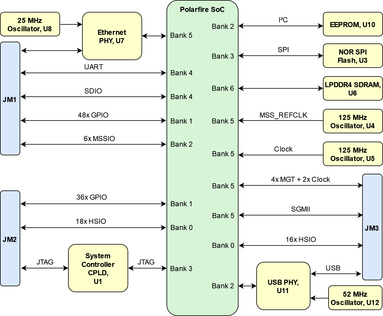
Trenz Electronic TEM0007 module is an industrial-grade FPGA micromodule integrating a Microsemi Polarfire SoC FPGA, Gigabit Ethernet PHY, USB PHY 2.0, one GByte DDR4 LPDDR4 SDRAM, 64 MByte SPI Flash memory for configuration and operation, and power supply. A large number of configurable I/Os is provided via robust board-to-board (B2B) connectors.
...
| Scroll Title |
|---|
| anchor | Figure_OV_BD |
|---|
| title | TExxxx TEM0007 block diagram |
|---|
|
| Scroll Ignore |
|---|
| draw.io Diagram |
|---|
| border | true |
|---|
| |
|---|
| diagramName | Figure_OV_BD |
|---|
| simpleViewer | true |
|---|
| width | |
|---|
| links | auto |
|---|
| tbstyle | top |
|---|
| diagramDisplayName | |
|---|
| lbox | true |
|---|
| diagramWidth | 644 |
|---|
| revision | 14 |
|---|
|
|
| Scroll Only |
|---|
|
|
...
| Scroll Title |
|---|
| anchor | Table_SIP_B2B |
|---|
| title | General SoC I/O to B2B connectors information |
|---|
|
| Scroll Table Layout |
|---|
| orientation | portrait |
|---|
| sortDirection | ASC |
|---|
| repeatTableHeaders | default |
|---|
| style | |
|---|
| widths | |
|---|
| sortByColumn | 1 |
|---|
| sortEnabled | false |
|---|
| cellHighlighting | true |
|---|
|
| FPGA Bank | B2B Connector | I/O Signal Count | Voltage Level | Notes |
|---|
| 0 | JM2 | 18 | 1.2 V / 1.35 V / 1.5 V / 1.8 V | HSIO dependent on VCCIOD | | 0 | JM3 | 16 | 1.2 V / 1.35 V / 1.5 V / 1.8 V | HSIO dependent on VCCIOD | | 1 | JM1 | 48 | 1.2 V / 1.5 V / 1.8 V / 2.5 V / 3.3 V | GPIO dependent on VCCIOB | | 1 | JM2 | 36 | 1.2 V / 1.5 V / 1.8 V / 2.5 V / 3.3 V | GPIO dependent on VCCIOB | | 4 | JM1 | 6 | 3.3 V | MSSIO | | 4 | JM1 | 6 | 3.3 V | SDIO - or MSSIO | | 4 | JM1 | 2 | 3.3 V | UART - or MSSIO | | 5 | JM3 | 4 | - | SGMII (1 pair for TX / 1 pair for RX) | | 5 | JM3 | 16 | - | SERDES (4 pairs for TX / 4 pairs for RX) | | 5 | JM3 | 4 | - | SERDES CLK (2 pairs for RX) |
|
...
| Scroll Title |
|---|
| anchor | Table_OBP_SDIO |
|---|
| title | SDIO interface description |
|---|
|
| Scroll Table Layout |
|---|
| orientation | portrait |
|---|
| sortDirection | ASC |
|---|
| repeatTableHeaders | default |
|---|
| style | |
|---|
| widths | |
|---|
| sortByColumn | 1 |
|---|
| sortEnabled | false |
|---|
| cellHighlighting | true |
|---|
|
| FPGA Bank 4 | Connected to | B2B | Notes |
|---|
| MSSIO0 - J1 | SDIO_CLK | JM1 - 27 |
| | MSSIO1 - K5 | SDIO_CMD | JM1 - 25 |
| | MSSIO2 - H1 | SDIO_DAT0 | JM1 - 23 |
| | MSSIO3 - J4 | SDIO_DAT1 | JM1 - 21 |
| | MSSIO4 - K4 | SDIO_DAT2 | JM1 - 19 |
| | MSSIO5 - J7 | SDIO_DAT3 | JM1 - 17 |
|
|
MSSIO
...
Interface
The MSSIO interface is Six MSSIOs are connected from the Polarfire SoC to the B2B connector.
...
On-board Gigabit Ethernet PHY (U7) is provided with Marvell Alaska 88E1512 IC (U7). The Ethernet PHY SGMII interface is connected to the Polarfire SoC.
...
| Scroll Title |
|---|
| anchor | Table_OBP |
|---|
| title | On board peripherals |
|---|
|
| Scroll Table Layout |
|---|
| orientation | portrait |
|---|
| sortDirection | ASC |
|---|
| repeatTableHeaders | default |
|---|
| style | |
|---|
| widths | |
|---|
| sortByColumn | 1 |
|---|
| sortEnabled | false |
|---|
| cellHighlighting | true |
|---|
|
EthernetFLASH| LPDDR4 | U6 | USB | U11 | |
SPI Flash Memory
| Page properties |
|---|
|
Notes : Minimum and Maximum density of quad SPI flash must be mentioned for other assembly options. |
The TEM0007 is equipped with a MT25QU512ABB8E12-0SIT flash memory chip, U3, which provided storage for FPGA configuration files. After configuration, the remaining free memory can be used for application data storage.
...
| anchor | Table_OBP_SPI |
|---|
| title | SPI Flash interface pins |
|---|
...
System Controller CPLD
The System Controller CPLD (U1) is provided by Lattice Semiconductor LCMXO2-256HC (MachXO2 product family). It is the central system management unit with module specific firmware installed to monitor and control various signals of the FPGA, on-board peripherals, I/O interfaces and module as a whole.
Gigabit Ethernet
On-board Gigabit Ethernet PHY (U7) is provided with Marvell Alaska 88E1512 IC (U7). The Ethernet PHY SGMII interface is connected to the Polarfire SoC. The reference clock input of the PHY is supplied from an on-board 25.00 MHz oscillator (U8).
| Scroll Title |
|---|
| anchor | Table_OBP_ETH |
|---|
| title | Ethernet PHY to Polarfire SoC connections |
|---|
|
| Scroll Table Layout |
|---|
| orientation | portrait |
|---|
| sortDirection | ASC |
|---|
| repeatTableHeaders | default |
|---|
| style | |
|---|
| widths | |
|---|
| sortByColumn | 1 |
|---|
| sortEnabled | false |
|---|
| cellHighlighting | true |
|---|
|
| SoC U2 | Signal Name | ETH | Signal Description |
|
|---|
Bank 5 - N6 | SGMII0_IN_P | U7 - 1 | SGMII Data Positive |
| | Bank 5 - N7 | SGMII0_IN_N | U7 - 2 | SGMII Data Negativ |
| Bank 5 - L5 | SGMII0_OUT_P | U7 - 4 | SGMII Data Positive |
| | Bank 5 - L6 | SGMII0_OUT_N | U7 - 5 | SGMII Data Negativ |
| | Bank 2 - D3 | ETH_MDC | U7 - 7 | Management Data Clock |
| | Bank 2 - C2 | ETH_MDIO | U7 - 8 | Management Date I/O |
| | Bank 2 - E5 | ETH_RST | U7 - 16 | Hardware Reset |
| | Bank 1 - AA16 | PHY_LED0 | U7 - 14 | LED Output | via voltage-level translator | | Bank 1 - Y16 | PHY_LED1 | U7 - 13 | LED Output | via voltage-level translator | | Bank 1 - Y14 | PHY_LED2 | U7 - 12 | LED Output | via voltage-level translator |
|
USB PHY
Hi-speed USB ULPI PHY (U11) is provided with USB3320 from Microchip. The ULPI interface is connected to the Polarfire SoC via MSSIO14...25 bank 2. The I/O voltage is fixed at 3.3 V and PHY reference clock input is supplied from the on-board 52.00 MHz oscillator (U12)
...
There is a 2 Kbit EEPROM provided on the module TEM0007 with a pre-programmed globally unique MAC.
| Scroll Title |
|---|
| anchor | Table_OBP_EEPUSB |
|---|
| title | I2C EEPROM interface MSSIOs and pinsUSB PHY to Polarfire SoC connections |
|---|
|
| Scroll Table Layout |
|---|
| orientation | portrait |
|---|
| sortDirection | ASC |
|---|
| repeatTableHeaders | default |
|---|
| style | |
|---|
| widths | |
|---|
| sortByColumn | 1 |
|---|
| sortEnabled | false |
|---|
| cellHighlighting | true |
|---|
|
|
| MSSIO Pin | Schematic | U10 Pin | Notes |
|---|
26 | I2C_SCL | SCL - 1 | 27 | I2C_SDA | SDA - 3 | | Scroll Title |
|---|
| anchor | Table_OBP_I2C_EEPROM |
|---|
| title | I2C address for EEPROM |
|---|
|
| Scroll Table Layout |
|---|
| orientation | portrait |
|---|
| sortDirection | ASC |
|---|
| repeatTableHeaders | default |
|---|
style | widths | | sortByColumn | 1 |
|---|
| sortEnabled | false |
|---|
| cellHighlighting | true |
|---|
| MSSIO Pin | I2C Address | Designator | Notes |
|---|
26...27 | 0x50 | U10 |
LEDs
...
| anchor | Table_OBP_LED |
|---|
| title | On-board LEDs |
|---|
| Bank 2 | Signal Name | USB | Signal Description |
|---|
U2 - G4 | OTG-STP | U11 - 29 | Stop | | U2 - G5 | OTG-NXT | U11 - 2 | Next | U2 - F1 | OTG-DIR | U11 - 31 | Direction | | U2 - G2 | OTG-CLK | U11 - 1 | Clock | | U2 - F2 | OTG_DATA0 | U11 - 3 | ULPI bi-directional data bus | | U2 -E1 | OTG_DATA1 | U11 - 4 | ULPI bi-directional data bus | | U2 -G3 | OTG_DATA2 | U11 - 5 | ULPI bi-directional data bus | | U2 -F5 | OTG_DATA3 | U11 - 6 | ULPI bi-directional data bus | | U2 - D1 | OTG_DATA4 | U11 - 7 | ULPI bi-directional data bus | | U2 -D2 | OTG_DATA5 | U11 - 9 | ULPI bi-directional data bus | | U2 -F6 | OTG_DATA6 | U11 - 10 | ULPI bi-directional data bus | | U2 - F3 | OTG_DATA7 | U11 - 13 | ULPI bi-directional data bus | | U2 - E4 | OTG-RST | U11 - 27 | Reset |
|
...
LPDDR4 SDRAM
| Page properties |
|---|
|
Notes : Minimum and Maximum density of DDR3 SDRAM must be mentioned for other assembly options. (pay attention to supported address length for DDR3) |
...
- Part number: IS43LQ32256A-062BLI
- Supply voltage: +1.8 V / +1.1 V
- Speed: 1600 MHz
- Temperature: Industrial (-40°C to +85°C)
USB PHY
- 062BLI
- Supply voltage: +1.8 V / +1.1 V
- Speed: 1600 MHz
- Temperature: Industrial (-40°C to +85°C)
EEPROM
There is a 2 Kbit EEPROM provided on the module TEM0007 with a pre-programmed globally unique MAC.Hi-speed USB ULPI PHY (U11) is provided with USB3320 from Microchip. The ULPI interface is connected to the Polarfire SoC via MSSIO14...25 bank 2. The I/O voltage is fixed at 3.3 V and PHY reference clock input is supplied from the on-board 52.00 MHz oscillator (U12).
| Scroll Title |
|---|
| anchor | Table_OBP_USBEEP |
|---|
| title | USB PHY to Polarfire SoC connectionsI2C EEPROM interface MSSIOs and pins |
|---|
|
| Scroll Table Layout |
|---|
| orientation | portrait |
|---|
| sortDirection | ASC |
|---|
| repeatTableHeaders | default |
|---|
| style | |
|---|
| widths | |
|---|
| sortByColumn | 1 |
|---|
| sortEnabled | false |
|---|
| cellHighlighting | true |
|---|
|
|
| Bank 2 | Signal Name | USB | Signal Description |
|---|
U2 - G4 | OTG-STP | U11 - 29 | Stop |
| U2 - G5 | OTG-NXT | U11 - 2 | Next |
U2 - F1 | OTG-DIR | U11 - 31 | Direction |
| U2 - G2 | OTG-CLK | U11 - 1 | Clock |
| U2 - F2 | OTG_DATA0 | U11 - 3 | ULPI bi-directional data bus |
| U2 -E1 | OTG_DATA1 | U11 - 4 | ULPI bi-directional data bus |
| U2 -G3 | OTG_DATA2 | U11 - 5 | ULPI bi-directional data bus |
| U2 -F5 | OTG_DATA3 | U11 - 6 | ULPI bi-directional data bus |
| U2 - D1 | OTG_DATA4 | U11 - 7 | ULPI bi-directional data bus |
| U2 -D2 | OTG_DATA5 | U11 - 9 | ULPI bi-directional data bus |
| U2 -F6 | OTG_DATA6 | U11 - 10 | ULPI bi-directional data bus |
| U2 - F3 | OTG_DATA7 | U11 - 13 | ULPI bi-directional data bus |
Gigabit Ethernet
| MSSIO Pin | Schematic | U10 Pin | Notes |
|---|
| 26 | I2C_SCL | SCL - 1 |
| | 27 | I2C_SDA | SDA - 3 |
|
|
| Scroll Title |
|---|
| anchor | Table_OBP_I2C_EEPROM |
|---|
| title | I2C address for EEPROM |
|---|
|
| Scroll Table Layout |
|---|
| orientation | portrait |
|---|
| sortDirection | ASC |
|---|
| repeatTableHeaders | default |
|---|
| style | |
|---|
| widths | |
|---|
| sortByColumn | 1 |
|---|
| sortEnabled | false |
|---|
| cellHighlighting | true |
|---|
|
| MSSIO Pin | I2C Address | Designator | Notes |
|---|
| MSSIO26...27 | 0x50 | U10 |
|
|
SPI Flash Memory
| Page properties |
|---|
|
Notes : Minimum and Maximum density of quad SPI flash must be mentioned for other assembly options. |
The TEM0007 is equipped with a MT25QU512ABB8E12-0SIT flash memory chip, U3, which provided storage for FPGA configuration files. After configuration, the remaining free memory can be used for application data storage.On-board Gigabit Ethernet PHY (U7) is provided with Marvell Alaska 88E1512 IC (U7). The Ethernet PHY SGMII interface is connected to the Polarfire SoC. The reference clock input of the PHY is supplied from an on-board 25.00 MHz oscillator (U8).
| Scroll Title |
|---|
| anchor | Table_OBP_ETHSPI |
|---|
| title | Ethernet PHY to Polarfire SoC connectionsSPI Flash interface pins |
|---|
|
| Scroll Table Layout |
|---|
| orientation | portrait |
|---|
| sortDirection | ASC |
|---|
| repeatTableHeaders | default |
|---|
| style | |
|---|
| widths | |
|---|
| sortByColumn | 1 |
|---|
| sortEnabled | false |
|---|
| cellHighlighting | true |
|---|
|
|
| Bank 5 | Signal Name | ETH | Signal Description |
|---|
U2 - N6 | SGMII0_IN_P | U7 - 1 | SGMII Data Positive |
| U2 - N7 | SGMII0_IN_N | U7 - 2 | SGMII Data Negativ |
U2 - L5 | SGMII0_OUT_P | U7 - 4 | SGMII Data Positive |
| U2 - L6 | SGMII0_OUT_N | U7 - 5 | SGMII Data Negativ |
System Controller CPLD
...
| Polarfire SoC Pin | Schematic | U3 Pin | Notes |
|---|
| SCK_3 - E6 | SPI_SCK | CLK - B2 |
| | SS_3 - G7 | SPI_SS | CS# - C2 |
| | SDO_3 - F7 | SPI_SDO | DI/IO0 - D3 |
| | SDI_3 - H10 | SPI_SDI | DO/IO1 - D2 |
| | SPI_EN_3 - H11 | SPI_EN | - |
|
|
Oscillators
| Scroll Title |
|---|
| anchor | Table_OBP_CLK |
|---|
| title | Osillators |
|---|
|
| Scroll Table Layout |
|---|
| orientation | portrait |
|---|
| sortDirection | ASC |
|---|
| repeatTableHeaders | default |
|---|
| style | |
|---|
| widths | |
|---|
| sortByColumn | 1 |
|---|
| sortEnabled | false |
|---|
| cellHighlighting | true |
|---|
|
| Designator | Description | Frequency | Note |
|---|
| U4 | MSS REFCLK | 125 MHz |
| | U5 | SERDES CLK | 125 MHz |
| | U12 | USB | 52 MHz |
|
|
...
| Page properties |
|---|
|
- This section is optional and only for modules.
use "include page" macro and link to the general B2B connector page of the module series,For example: 6 x 6 SoM LSHM B2B Connectors
| Include Page |
|---|
PD:6 x 6 SoM LSHM B2B Connectors | PD:6 x 6 SoM LSHM B2B Connectors |
|
? x ? modules use two or three Samtec Micro Tiger Eye Connector on the bottom side.
3 x REF-??????? (compatible to ????????), (?? pins, ?? per row)
| Include Page |
|---|
| PD:4 x 5 SoM LSHM B2B Connectors |
|---|
| PD:4 x 5 SoM LSHM B2B Connectors |
|---|
|
...
Technical Specifications
Absolute Maximum Ratings
...