...
| Scroll Title |
|---|
| anchor | Figure_OV_BD |
|---|
| title | TEMB0005 block diagram |
|---|
|
| Scroll Ignore |
|---|
| draw.io Diagram |
|---|
| border | false |
|---|
| |
|---|
| diagramName | TEMB0005_OV_BD |
|---|
| simpleViewer | false |
|---|
| width | |
|---|
| links | auto |
|---|
| tbstyle | hidden |
|---|
| diagramDisplayName | |
|---|
| lbox | true |
|---|
| diagramWidth | 640 |
|---|
| revision | 23 |
|---|
|
|
| Scroll Only |
|---|

|
|
Main Components
...
| Scroll Title |
|---|
| anchor | Figure_OV_MC |
|---|
| title | TEMB0005 main components |
|---|
|
| Scroll Ignore |
|---|
| draw.io Diagram |
|---|
| border | false |
|---|
| |
|---|
| diagramName | TEMB0005_OV_MC |
|---|
| simpleViewer | false |
|---|
| width | |
|---|
| links | auto |
|---|
| tbstyle | hidden |
|---|
| diagramDisplayName | |
|---|
| lbox | true |
|---|
| diagramWidth | 641 |
|---|
| revision | 45 |
|---|
|
|
| Scroll Only |
|---|
|
|
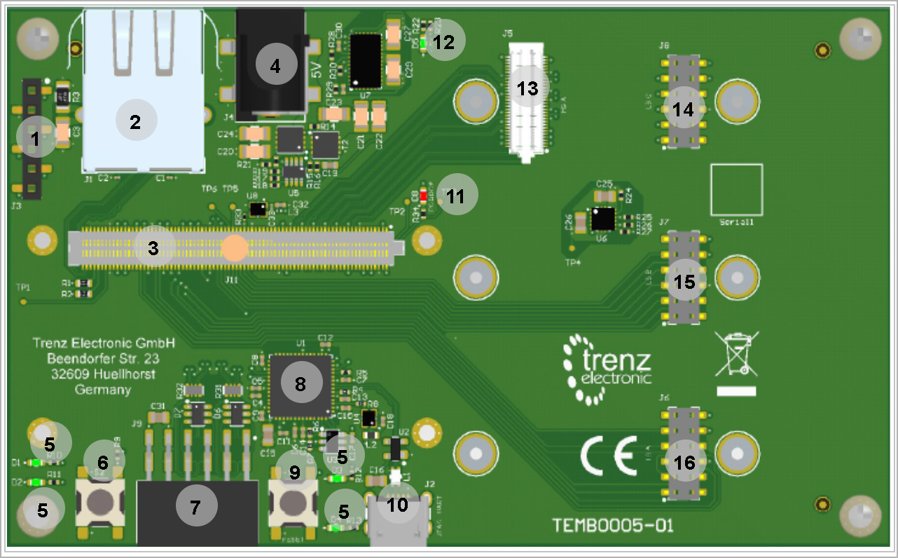
- SMD Header 6x1, J3
- RJ45 LAN Socket, J1
- B2B Razor Beam Connector, J11
- Barrel Jack, J4
- Green LEDs, D1...4
- User Push Button, S2
- PMod 2x6 SMD Host Socket, J9
- FT2232H FTDI, U1
- Reset Push Button, S1
- Micro USB2.0 Socket, J2
- Red LED (PG_DCDC), D8
- Green LED (5VIN), D5
- B2B Mezzanine Connector, J5
- Dual Wipe Socket, J8
- Dual Wipe Socket, J7
- Dual Wipe Socket, J6
...
| Scroll Title |
|---|
| anchor | Table_OBP |
|---|
| title | On board peripherals |
|---|
|
| Scroll Table Layout |
|---|
| orientation | portrait |
|---|
| sortDirection | ASC |
|---|
| repeatTableHeaders | default |
|---|
| style | |
|---|
| widths | |
|---|
| sortByColumn | 1 |
|---|
| sortEnabled | false |
|---|
| cellHighlighting | true |
|---|
|
| Chip/Interface | Designator | Notes |
|---|
| FTDI | U1 |
| | LEDs | D1...D5 |
| | Push Buttons | S1-S2 |
| | EEPROM | U3 |
| | Oscillator | U4-U8
|
|
|
EEPROM
There is an EEPROM IC, U3 provided for storing the FTDI (U1) configuration.
| Scroll Title |
|---|
| anchor | Table_OBP_EEP |
|---|
| title | I2C EEPROM interface MIOs and pins |
|---|
|
| Scroll Table Layout |
|---|
| orientation | portrait |
|---|
| sortDirection | ASC |
|---|
| repeatTableHeaders | default |
|---|
| style | |
|---|
| widths | |
|---|
| sortByColumn | 1 |
|---|
| sortEnabled | false |
|---|
| cellHighlighting | true |
|---|
|
| MIO Pin | Schematic | U?? Pin | Notes | Notes |
|---|
| DI/DO | EEDATA |
| | CLK | EECLK |
| | CS | EECS |
|
|
| Scroll Title |
|---|
| anchor | Table_OBP_I2C_EEPROM |
|---|
| title | I2C address for EEPROM |
|---|
|
| Scroll Table Layout |
|---|
| orientation | portrait |
|---|
| sortDirection | ASC |
|---|
| repeatTableHeaders | default |
|---|
| style | |
|---|
| widths | |
|---|
| sortByColumn | 1 |
|---|
| sortEnabled | false |
|---|
| cellHighlighting | true |
|---|
|
| MIO Pin | I2C Address | Designator | Notes |
|---|
|
|
|
|
|
...
| Scroll Title |
|---|
| anchor | Table_OBP_LED |
|---|
| title | On-board LEDs |
|---|
|
| Scroll Table Layout |
|---|
| orientation | portrait |
|---|
| sortDirection | ASC |
|---|
| repeatTableHeaders | default |
|---|
| style | |
|---|
| widths | |
|---|
| sortByColumn | 1 |
|---|
| sortEnabled | false |
|---|
| cellHighlighting | true |
|---|
|
| Designator | Color | Connected to | Active Level | Note |
|---|
| D1...D4 | Green | B2B, J11 | Active High |
D5| User LEDS | | D5 | Green | 5VIN | Active High | Power Status LED | | D6 | Red | PG_DCDC | Active Low |
|
...
Clock Sources
| Scroll Title |
|---|
| anchor | Table_OBP_CANCLK |
|---|
| title | CAN Tranciever interface MIOsOsillators |
|---|
|
| Scroll Table Layout |
|---|
| orientation | portrait |
|---|
| sortDirection | ASC |
|---|
| repeatTableHeaders | default |
|---|
| style | |
|---|
| widths | |
|---|
| sortByColumn | 1 |
|---|
| sortEnabled | false |
|---|
| cellHighlighting | true |
|---|
|
Bank| Schematic | U?? Pin | Notes | D-Tx | Driver Input | R-Rx | Reciever Output | |
...
| anchor | Table_OBP_CLK |
|---|
| title | Osillators |
|---|
| Description | Frequency | Note |
|---|
| U4 | MEMS Oscillator | 12 MHz |
| | U8 | MEMS Oscillator | 30 MHz |
|
...
Programmable Clock Generator
There is a programmable clock generator on-board (U??) provided in order to generate variable clocks for the module. Programming can be done using I2C via PIN header J??. The I2C Address is 0x??.
| Scroll Title |
|---|
| anchor | Table_OBP_PCLK |
|---|
| title | Programmable Clock Generator Inputs and Outputs |
|---|
|
| Scroll Table Layout |
|---|
| orientation | portrait |
|---|
| sortDirection | ASC |
|---|
| repeatTableHeaders | default |
|---|
| sortByColumn | 1 |
|---|
| sortEnabled | false |
|---|
| cellHighlighting | true |
|---|
|
U?? Pin
| Signal | Connected to | Direction | Note |
|---|
IN0 | IN1 | IN2 | IN3 | XAXB | SCLK | SDA | OUT0 | OUT1 | OUT2 | OUT3 | OUT4 | OUT5 | OUT6 | OUT7 | OUT8/OUT9
|
Power and Power-On Sequence
...