Versions Compared

Key

  • This line was added.
  • This line was removed.
  • Formatting was changed.

...

Page properties
hiddentrue
idComments

Note:
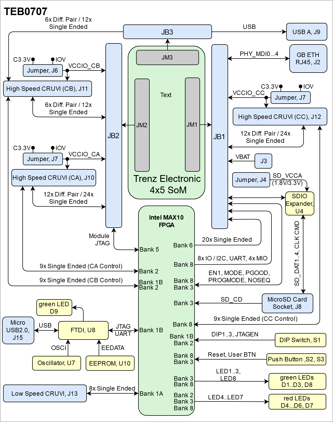
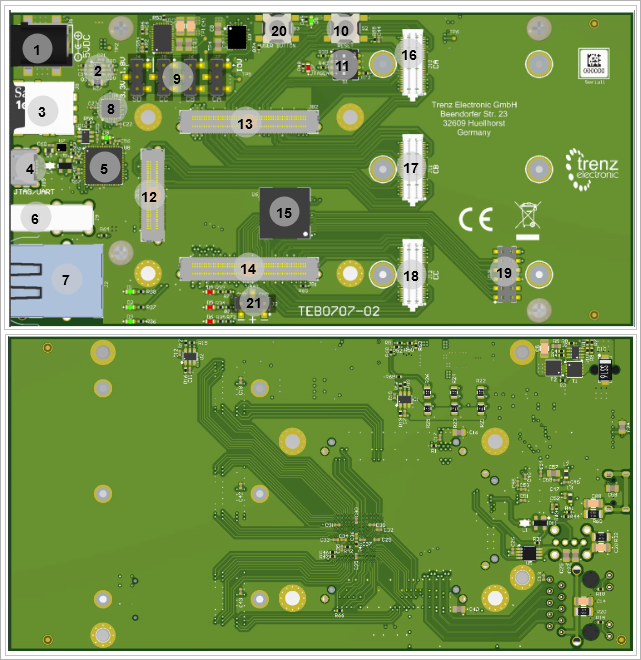
 'description: Important components and connector or other Features of the module
→ please sort and indicate assembly options

Key Features'  must be split into 6 main groups for modules and mainboards:

  • SoC/FPGA
    • Package: SFVC784
    • Device: ZU2...ZU5*
    • Engine: CG, EG, EV*
    • Speed: -1LI, -2LE,*, **
    • Temperature: I, E,*, **
  • RAM/Storage
    • Low Power DDR4 on PS
      • Data width: 32bit
      • Size: def. 2GB*
      • Speed:***
    • eMMC
      • Data width: 8Bit
      • size: def. 8GB *
    • QSPI boot Flash in dual parallel mode (size depends on assembly version)
      • Data width: 8bit
      • size: def. 128MB *
    • HyperRAM/Flash (optional, default not assembled)
      • size:*
    • MAC address serial EEPROM with EUI-48™ node identity (Microchip 24AA025E48)
  • On Board
    • Lattice LCMXO2
    • PLL SI5338
    • Gigabit Ethernet transceiver PHY (Marvell Alaska 88E1512)
    • Hi-speed USB2 ULPI transceiver with full OTG support (Microchip USB3320C)
  • Interface
    • 132 x HP PL I/Os (3 banks)
    • ETH
    • USB
    • 4 GTR (for USB3, Sata, PCIe, DP)
    • MIO for UART
    • MIO for SD
    • MIO for PJTAG
    • JTAG
    • Ctrl
  • Power
    • 3.3V-5V Main Input
    • 3.3V Controller Input
    • Variable Bank IO Power Input
  • Dimension
    • 4 cm x 5 cm
  • Notes
    • * depends on assembly version
    • ** also non low power assembly options possible
    • *** depends on used U+ Zynq and DDR4 combination


Key Features'  must be split into 6 main groups for carrier:

  • Modules
    • TE0808, TE807, TE0803,...
  • RAM/Storage
    • E.g. SDRAM, SPI
  • On Board
    • E.g. CPLD, PLL
  • Interface
    • E.g. ETH, USB, B2B, Display port
  • Power
    • E.g. Input supply voltage
  • Dimension


  • Modules
    • TE0820
  • RAM/Storage
    • eMMC
      • Data width: 8Bit
      • size: def. 8GB *
    • QSPI boot Flash in dual parallel mode (size depends on assembly version)
      • Data width: 8bit
      • size: def. 128MB *
    • HyperRAM/Flash (optional, default not assembled)
      • size:*
    • MAC address serial EEPROM with EUI-48™ node identity (Microchip 24AA025E48)
  • On Board
    • Intel Max 10 FPGA
    • FTDI FT2223
    • 8x Green User LEDs
    • DIP Switch
    • Push Buttons
  • Interface
    • Gigabit RJ45 LAN socket
    • SD Card socket
  • Power
    • 5V Input Power Supply 
  • Dimension
    • ...
  • Notes
    • ...
    • Micro USB2.0 Socket
    • Miceo USB A Socket
    • 6x High Speed B2B Connectors,
    • 1x Low Speed B2B Connector
    • 4x Jumpers
  • Power
    • 5V Input Power Supply 
  • Dimension
    • 135 x 68 mm
  • Notes


Block Diagram

Page properties
hiddentrue
idComments

add drawIO object here.

Note

For more information regarding how to draw a diagram, Please refer to "Diagram Drawing Guidline" .


...

Scroll Title
anchorFigure_OV_BD
titleTEB0707 block diagram


Scroll Ignore

draw.io Diagram
borderfalse
diagramNameTEB0707_OV_BD
simpleViewerfalse
width639
linksauto
tbstylehidden
diagramDisplayName
lboxtrue
diagramWidth641
revision1


Scroll Only

|


Main Components

Page properties
hiddentrue
idComments

Notes :

  • Picture of the PCB (top and bottom side) with labels of important components
  • Add List below


Note

For more information regarding how to add board photoes, Please refer to "Diagram Drawing Guidline" .


...

Scroll Title
anchorFigure_OV_MC
titleTEB0707 main components


Scroll Ignore
draw.io Diagram
borderfalse
diagramNameTEB0707_OV_MC
simpleViewerfalse
width639
linksauto
tbstylehidden
diagramDisplayName
lboxtrue
diagramWidth641
revision3
Scroll Only

Image Removed

4


Scroll Only

Image Added


  1. Barrel Jack Power Supply, J1
  2. Voltage Regulator, U1
  3. Micro SD Card Socket, J8
  4. Micro USB2.0 Socket, J15
  5. FT2232H FTDI, U8
  6. Micro USB A Socket, J9
  7. RJ45 LAN Socket, J2
  8. SDIO Port Expander, U4
  9. Jumpers, J4...7
  10. Push Button (Reset), S2
  11. DIP Switch, S1
  12. High Speed B2B Connector, JB3
  13. High Speed B2B Connector, JB2
  14. High Speed B2B Connector, JB1
  15. Intel MAX 10 FPGA, U6
  16. High speed B2B Connector, J10
  17. High speed B2B Connector, J11
  18. High speed B2B Connector, J12
  19. Low Speed Connector, J13
  20. User Push Button, S3
  21. Jumper, J3
  22. ...
  23. ...
  24. ...

Initial Delivery State

Page properties
hiddentrue
idComments

Notes :

Only components like EEPROM, QSPI flash can be initialized by default at manufacture.

If there is no components which might have initial data ( possible on carrier) you must keep the table empty

...

Include Page
IN:Legal Notices
IN:Legal Notices


draw.io Diagram
borderfalse
diagramNameTEB0707_OV_MC
simpleViewerfalse
width639
linksauto
tbstylehidden
diagramDisplayName
lboxtrue
diagramWidth641
revision3