...
- Modules
- RAM/Storage
- EEPROM (FTDI Configuration)
- On Board
- Intel Max 10 FPGA
- FTDI FT2223
- 8x Green User LEDs
- DIP Switch
- Push Buttons
- Interface
- Gigabit RJ45 LAN socket
- SD Card socket
- Micro USB2.0 Socket
- Miceo Micro USB A Socket
- 6x 3x High Speed B2B Connectors
- 3x CRUVI Connectors,
- 1x Low Speed B2B Connector
- 4x Jumpers
- Power
- Dimension
- Notes
...
| Scroll Title |
|---|
| anchor | Figure_OV_BD |
|---|
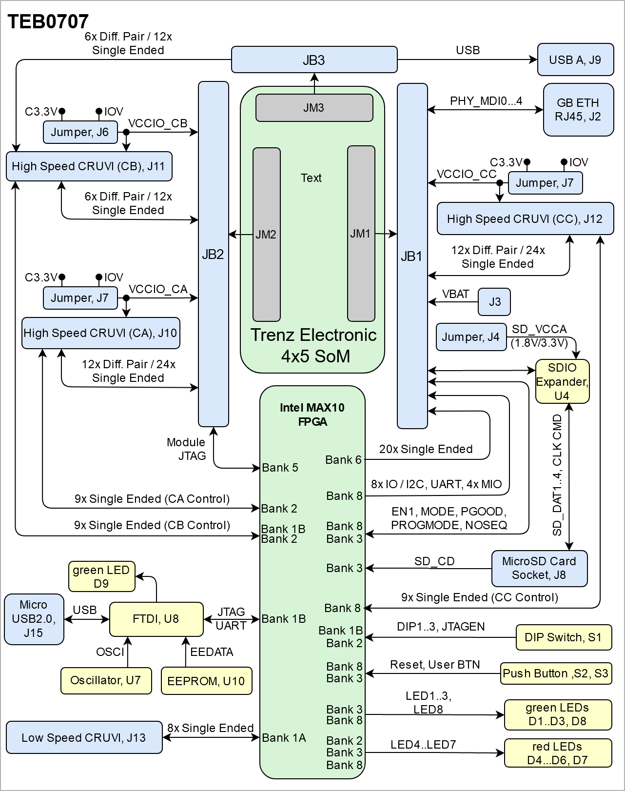
| title | TEB0707 block diagram |
|---|
|
| Scroll Ignore |
|---|
| draw.io Diagram |
|---|
| border | false |
|---|
| |
|---|
| diagramName | TEB0707_OV_BD |
|---|
| simpleViewer | false |
|---|
| width | 639 |
|---|
| links | auto |
|---|
| tbstyle | hidden |
|---|
| diagramDisplayName | |
|---|
| lbox | true |
|---|
| diagramWidth | 641 |
|---|
| revision | 13 |
|---|
|
|
| Scroll Only |
|---|
| |
|
Main Components
| Page properties |
|---|
|
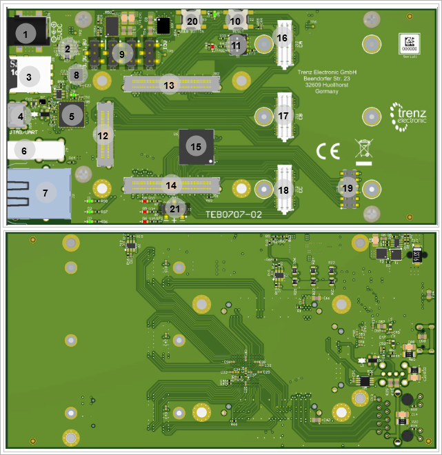
Notes : - Picture of the PCB (top and bottom side) with labels of important components
- Add List below
| Note |
|---|
For more information regarding how to add board photoes, Please refer to "Diagram Drawing Guidline" . | draw.io Diagram |
|---|
| border | false |
|---|
| |
|---|
| diagramName | TEB0707_OV_BD |
|---|
| simpleViewer | false |
|---|
| width | 639 |
|---|
| links | auto |
|---|
| tbstyle | hidden |
|---|
| diagramDisplayName | |
|---|
| lbox | true |
|---|
| diagramWidth | 641 |
|---|
| revision | 3 |
|---|
|
|
|
| Scroll Title |
|---|
| anchor | Figure_OV_MC |
|---|
| title | TEB0707 main components |
|---|
|
| Scroll Ignore |
|---|
| draw.io Diagram |
|---|
| border | false |
|---|
| |
|---|
| diagramName | TEB0707_OV_MC |
|---|
| simpleViewer | false |
|---|
| width | 639 |
|---|
| links | auto |
|---|
| tbstyle | hidden |
|---|
| diagramDisplayName | |
|---|
| lbox | true |
|---|
| diagramWidth | 641 |
|---|
| revision | 4 |
|---|
|
|
| Scroll Only |
|---|
|
|
...
The TEMB0707 is equipped with three a Low Speed Connectors J6...8 and a J 13 and three High Speed Connector J5J10...12. These connectors are provided for CRUVI extension cards. More information is provided in the B2B Connectors section.
...
There is a USB2.0 Socket, J2 J15 provided in order to communicate with the FTDI, U1U8. Data signals from USB2.0 are passed through a Line Filter L1 L4 and a Diode U2 U9 in order to be protected against inverse polarity connection.
| Scroll Title |
|---|
| anchor | Table_SIP_USB2 |
|---|
| title | USB2.0 Socket information |
|---|
|
| Scroll Table Layout |
|---|
| orientation | portrait |
|---|
| sortDirection | ASC |
|---|
| repeatTableHeaders | default |
|---|
| style | |
|---|
| widths | |
|---|
| sortByColumn | 1 |
|---|
| sortEnabled | false |
|---|
| cellHighlighting | true |
|---|
|
| Pin | Schematic | Connected to | Notes |
|---|
| ID | N.C | N.C |
| | D+ | DLUSB_P | FTDI, U1U8 | Through Line Filter, L1L4 | | D- | DLUSB_N | FTDI, U1U8 | Through Line Filter, L1L4 | | Vbus | VBUS | Diode, U2U9 |
|
|
Micro USB A
| Scroll Title |
|---|
| anchor | Table_SIP_USBA |
|---|
| title | USB2.0 Socket information |
|---|
|
| Scroll Table Layout |
|---|
| orientation | portrait |
|---|
| sortDirection | ASC |
|---|
| repeatTableHeaders | default |
|---|
| style | |
|---|
| widths | |
|---|
| sortByColumn | 1 |
|---|
| sortEnabled | false |
|---|
| cellHighlighting | true |
|---|
|
| Pin | Schematic | Connected to | Notes |
|---|
| ID | N.C | N.C |
| | D+ | DL_P | FTDI, U1 | Through Line Filter, L1 | | D- | DL_N | FTDI, U1 | Through Line Filter, L1 | | Vbus | VBUS | Diode, U2 |
|
|
...
There is a RJ45 Ethernet LAN Socket, J1 J2 connected to B2B, J11 JB1 via 2x 4x channels data receive and transmit.
| Scroll Title |
|---|
| anchor | Table_SIP_ETH |
|---|
| title | RJ45 LAN Socket information |
|---|
|
| Scroll Table Layout |
|---|
| orientation | portrait |
|---|
| sortDirection | ASC |
|---|
| repeatTableHeaders | default |
|---|
| style | |
|---|
| widths | |
|---|
| sortByColumn | 1 |
|---|
| sortEnabled | false |
|---|
| cellHighlighting | true |
|---|
|
| Pin | Schematic | Connected to | Notes |
|---|
| TD+2 | ETH1PHY_TXMDI0_P | B2B, J11JB1 | TD-
| | 3 | ETH1PHY_ | TXMDI0_N | B2B, | J11JB1 |
| RD+| 4 | ETH1PHY_ | RXMDI1_P | B2B, | J11JB1 | RD-
| | 5 | ETH1PHY_ | RXMDI1_N | B2B, | J11JB1 | Green LED | ETH1_LED0
| | 6 | PHY_MDI2_P | B2B, JB1 |
| | 7 | PHY_MDI2_N | B2B, JB1 |
| | 8 | PHY_MDI3_P | B2B, JB1 |
| | 9 | PHY_MDI3_N | B2B, JB1 |
| | VCC | ETH-VCC | B2B, JB1 |
| | Green LED | ETH1_LED0 | Intel MAX 10, U6 | Link/Activity indicator | | Yellow LED | ETH1_LED1 | Intel MAX 10, U6 | J11Link/Activity indicator | Yellow LED | ETH1_LED1 | B2B, J11 | Speed indicator |
|
Test Points
...
| Scroll Title |
|---|
| anchor | Table_OBP |
|---|
| title | On board peripherals |
|---|
|
| Scroll Table Layout |
|---|
| orientation | portrait |
|---|
| sortDirection | ASC |
|---|
| repeatTableHeaders | default |
|---|
| style | |
|---|
| widths | |
|---|
| sortByColumn | 1 |
|---|
| sortEnabled | false |
|---|
| cellHighlighting | true |
|---|
|
| Chip/Interface | Designator | Notes |
|---|
|
Quad SPI Flash Memory
| Intel MAX 10 | U6 |
| | FTDI | U8 |
| | SDIO Expander | U4 |
| | EEPROM | U10 |
| | Oscillator | U7 |
| | LEDs | D1...8 |
|
|
Quad SPI Flash Memory
| Page properties |
|---|
|
| Page properties |
|---|
|
Notes : Minimum and Maximum density of quad SPI flash must be mentioned for other assembly options. |
...
| Scroll Title |
|---|
| anchor | Table_OBP_LED |
|---|
| title | On-board LEDs |
|---|
|
| Scroll Table Layout |
|---|
| orientation | portrait |
|---|
| sortDirection | ASC |
|---|
| repeatTableHeaders | default |
|---|
| style | |
|---|
| widths | |
|---|
| sortByColumn | 1 |
|---|
| sortEnabled | false |
|---|
| cellHighlighting | true |
|---|
|
| Designator | Color | Connected to | Active Level | Note |
|---|
|
|
|
|
|
|
|
|
|
|
|
|
|
|
|
|
EEPROM
| Scroll Title |
|---|
| anchor | Table_OBP_EEP |
|---|
| title | I2C EEPROM interface MIOs and pins |
|---|
|
| Scroll Table Layout |
|---|
| orientation | portrait |
|---|
| sortDirection | ASC |
|---|
| repeatTableHeaders | default |
|---|
| style | |
|---|
| widths | |
|---|
| sortByColumn | 1 |
|---|
| sortEnabled | false |
|---|
| cellHighlighting | true |
|---|
|
| Pin | Schematic | Connected to | Notes |
|---|
| CS | EECS | FTDI, U8 |
| | CLK | EECLK | FTDI, U8 |
| | DIN | EEDATA | FTDI, U8 |
|
|
| Scroll Title |
|---|
| anchor | Table_OBP_I2C_EEPROM |
|---|
| title | I2C address for EEPROM |
|---|
|
| Scroll Table Layout |
|---|
| orientation | portrait |
|---|
| sortDirection | ASC |
|---|
| repeatTableHeaders | default |
|---|
| style | |
|---|
| widths | |
|---|
| sortByColumn | 1 |
|---|
| sortEnabled | false |
|---|
| cellHighlighting | true |
|---|
|
| I2C Address | Designator | Notes |
|---|
| A0 | U15 |
|
|
Ethernet
| Scroll Title |
|---|
| anchor | Table_OBP_ETH |
|---|
| title | Ethernet PHY to Zynq SoC connections |
|---|
|
| Scroll Table Layout |
|---|
| orientation | portrait |
|---|
| sortDirection | ASC |
|---|
| repeatTableHeaders | default |
|---|
| style | |
|---|
| widths | |
|---|
| sortByColumn | 1 |
|---|
| sortEnabled | false |
|---|
| cellHighlighting | true |
|---|
|
| U?? Pin | Signal Name | Connected to | Signal Description | Note |
|---|
|
|
|
|
|
|
|
|
|
|
|
|
|
|
|
|
|
|
|
|
|
|
|
|
|
|
|
|
|
|
|
|
|
|
|
|
|
|
|
|
|
|
|
|
|
|
|
|
|
|
|
|
|
|
|
|
|
|
|
|
|
|
|
|
|
|
|
|
|
|
|
...