Page History
...
Overview
The Trenz Electronic TE0022-02 is TE0022is a SoC board based on Intel Cyclone V FPGA, an ethernet Ethernet PHY, one GByte DDR3 SDRAM per HPS and FPGA and one 32 MByte Quad SPI Flash memory for configuration and operation per HPS and FPGA, and powerful switching-mode power supplies for all on-board voltages.
...
| Scroll Title | |||||||||||||||||||||||||||||||||||||||||||
|---|---|---|---|---|---|---|---|---|---|---|---|---|---|---|---|---|---|---|---|---|---|---|---|---|---|---|---|---|---|---|---|---|---|---|---|---|---|---|---|---|---|---|---|
| |||||||||||||||||||||||||||||||||||||||||||
|
The FMC connector provides further interfaces like JTAG and I²C:
...
| Scroll Title | |||||||||||||||||||||||||||||||||||||||||||||||||||||||||||||||||||||||||||
|---|---|---|---|---|---|---|---|---|---|---|---|---|---|---|---|---|---|---|---|---|---|---|---|---|---|---|---|---|---|---|---|---|---|---|---|---|---|---|---|---|---|---|---|---|---|---|---|---|---|---|---|---|---|---|---|---|---|---|---|---|---|---|---|---|---|---|---|---|---|---|---|---|---|---|---|
| |||||||||||||||||||||||||||||||||||||||||||||||||||||||||||||||||||||||||||
|
System Controller Intel MAX 10
...
Please refer to the section "Micro USB Connector (JTAG)".
FTDI (UART)
Please refer to the section "Micro USB Connector (UART)".
DIP-Switches
There are three 4-bit DIP-switches present on the TEI0022 board to configure options and set parameters. The following section describes the functionalities of the particular switches.
...
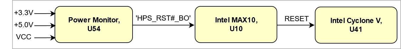
The following figures delivers the power-on sequence information. The figure Power Sequency shows the connections between the power devices and its management. The figure Suggested Power Sequency shows the recommended firmware power-on sequence. For more information about firmware depended power-on sequencing see TEI0022 Intel MAX 10 → Power mangement.
...
The voltages +3.3V, +5.0V, and VCC are monitored by the voltage monitor circuit LTC2911 (U54), which generates a reset signal at power-on. A manual reset is also possible as described in the reset table.
| Scroll Title | ||||||||||||||||||||||||||||||||
|---|---|---|---|---|---|---|---|---|---|---|---|---|---|---|---|---|---|---|---|---|---|---|---|---|---|---|---|---|---|---|---|---|
| ||||||||||||||||||||||||||||||||
|
...
Overview
Content Tools