Page History
...
- Digilent Pmod interface compatible
- Dual CAN FD PHY's (CAN0 and CAN1)
- Texas Instruments TCAN337G
- Up to 5Mbit data rate
- Compatible with ISO 11898-2
- Bus pin fault protection of ±14 V
Integrated 12 kV IEC-61000-4-2 ESD contact discharge protection
- 10 pin headers (IDC cable to DB9)
- One CAN FD transceiver has extra 3-pin screw connector terminal
- Single 3.3V supply
Main Components
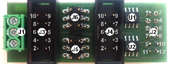
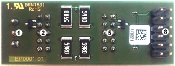
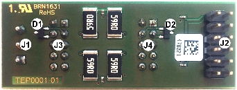
J1. Screw connector terminal of CAN0 bus
...
U1. Texas Instruments TCAN337G CAN FD transceiver, CAN0
D1. Bourns CDSOT23-T24CAN CANbus Protector, CAN0
U2. Texas Instruments TCAN337G CAN FD transceiver, CAN1
D2. Bourns CDSOT23-T24CAN CANbus Protector, CAN1
Interfaces and Pins
J1 Connector, CAN0 Bus
| Pin | Signal | Notes |
|---|---|---|
| 1 | CAN0_P | U1 high level CAN bus line |
| 2 | GND | U1 ground connection |
| 3 | CAN0_N | U1 low level CAN bus line |
J2 Connector, Pmod Interface
| Pin | Signal | Notes | Pin | Signal | Notes | |
|---|---|---|---|---|---|---|
| 1 | CAN0_TX | U1 CAN CAN0 transmit data input, integrated pull up | 2 | CAN1_TX | U2 CAN CAN1 transmit data input, integrated pull up | |
| 3 | CAN0_RX | U1 CAN CAN0 receive data output, tri-state | 4 | CAN1_RX | U2 CAN CAN1 receive data output, tri-state | |
| 5 | CAN0_S | U1 silent mode,integrated pull down | 6 | CAN1_S | U2 silent mode, integrated pull down | |
| 7 | CAN0_F | U1 open drain fault output | 8 | CAN1_F | U2 open drain fault output | |
| 9 | GND | U1 ground connection | 10 | GND | U2 ground connection | |
| 11 | 3.3V | U1 3.3-V 3V supply voltage | 12 | 3.3V | U2 3.3-V 3V supply voltage |
J3 Connector, CAN0 Bus
| Pin | Signal | Notes | Pin | Signal | Notes | |
|---|---|---|---|---|---|---|
| 1 | N/A | - | 2 | GND | U1 ground connection | |
| 3 | CAN0_N | U1 low level CAN bus line | 4 | CAN0_P | U1 high level CAN bus line | |
| 5 | GND | U1 ground connection | 6 | N/A | - | |
| 7 | N/A | - | 8 | N/A | - | |
| 9 | N/A | - | 10 | N/A | - |
J4 Connector, CAN1 Bus
| Pin | Signal | Notes | Pin | Signal | Notes | |
|---|---|---|---|---|---|---|
| 1 | N/A | - | 2 | GND | U2 ground connection | |
| 3 | CAN1_N | U2 low level CAN bus line | 4 | CAN1_P | U2 high level CAN bus line | |
| 5 | GND | U2 ground connection | 6 | N/A | - | |
| 7 | N/A | - | 8 | N/A | - | |
| 9 | N/A | - | 10 | N/A | - |
J5 Jumper Block/Connector CAN1 bus
Place jumpers on Close pins 1-3 and 2-4 with jumpers to activate enable on-board CAN bus terminator of U2terminator for CAN1 bus. J5 header can also be used as CAN CAN1 bus connector, refer to table below for pin mapping.
| Pin | Signal | Note | Pin | Signal | Note | |
|---|---|---|---|---|---|---|
| 3 | CAN1_N | U2 low level CAN bus line | 4 | CAN1_P | U2 high level CAN bus line | |
| 5 | GND | U2 ground connection | 6 | GND | U2 ground connection |
J6 Jumper Block/Connector
...
, CAN0 bus
Close Place jumpers on pins 1-3 and 2-4 with jumpers to activate enable on-board CAN bus terminator of U2. J5 terminator for CAN0 bus. J6 header can also be used as CAN CAN0 bus connector, refer to table below for pin mapping.
...
Module size: 54 mm × 20.5 mm.
Mating height of the J8 J2 connector from the PCB: 8mm
PCB thickness: 1.6mm
Highest part on PCB J1, J2 J3 and J5 J4 connectors, approximately 9.5mm from the PCB.
...
Overview
Content Tools