Page History
...
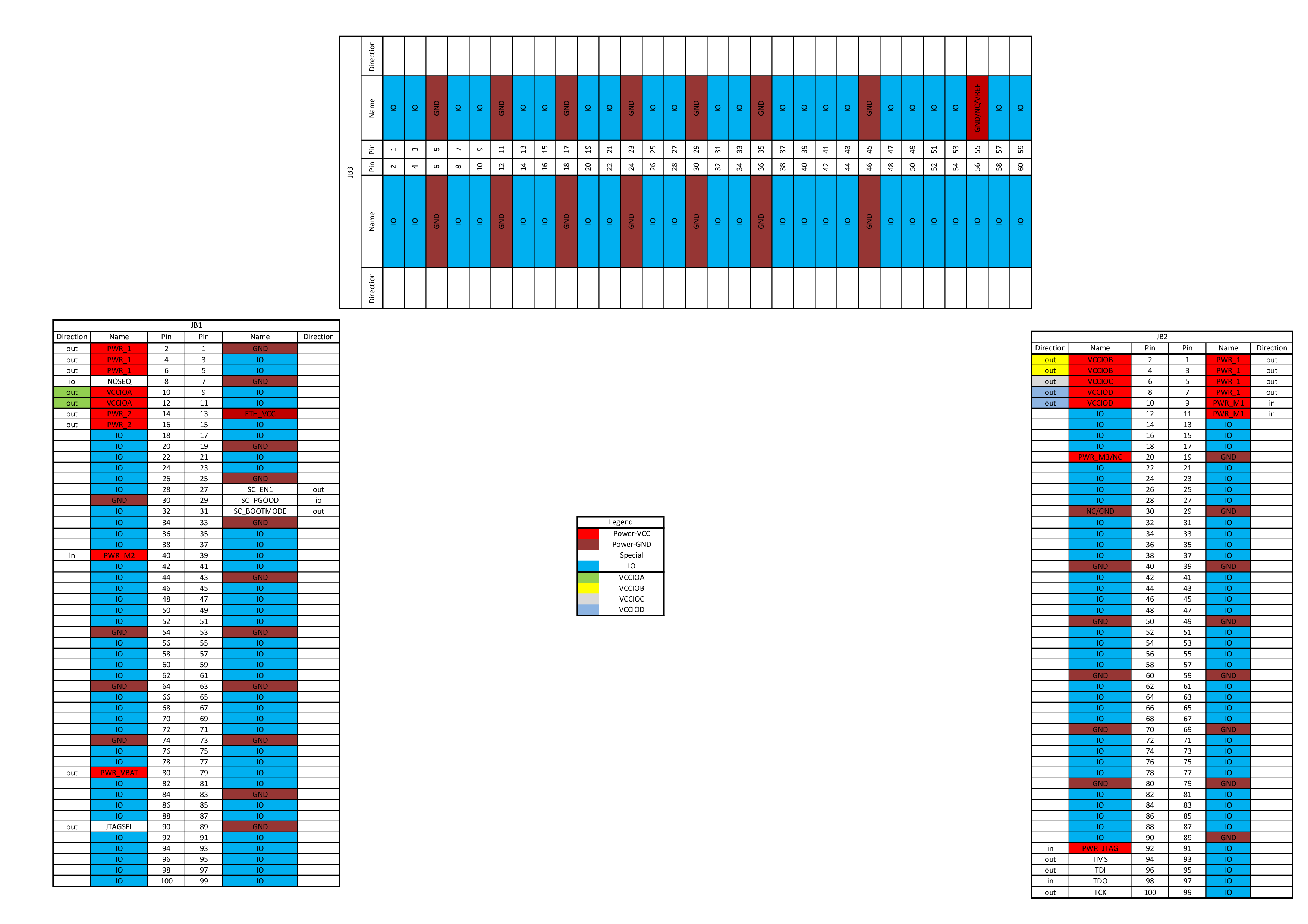
- Find your module model on the Module Power Connection Table and check the power supply of the different FPGA banks.
- If the power supply is variable(colored), go to the Carrier Board Power Connection Table and see how it's connected on your carrier board. Often the power source can be selected by jumper, resistor or variable used from other connector pin of the carrier board. So use the schematic name or the component designator from the table to search for the available options in the PCB schematics or TRM.
...
Attention: On some carrier boards the user supplied I/O voltages are connected together (red colored schematic names).
| Scroll Title | ||
|---|---|---|
| ||
|
Overview
Content Tools