Page History
...
Power comparison of all 4x5 carrier boards. *Power direction based on carrier boards view.There are 4 variable user supplied I/O voltages (VCCIOA, VCCIOB, VCCIOC and VCCIOD). PWR_1 and PWR_2 are fixed from carrier boards. PWR_M1 and PWR_M2 normally use default value from module. NC=Not Connected
Atte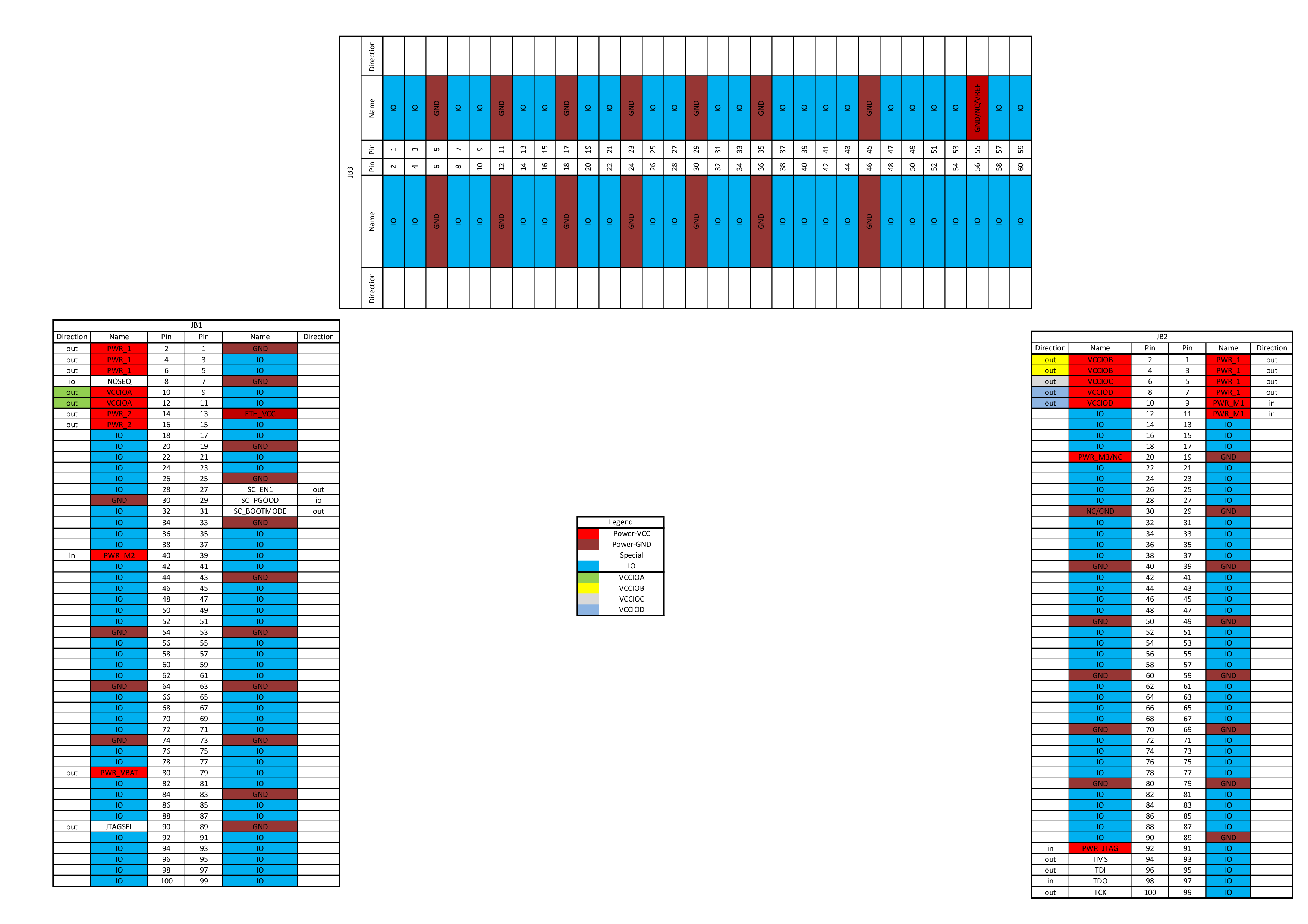 ntionAttention: On some carrier boards the user supplied I/O voltages are connected together (red colored schematic names).
...
| Scroll Title | ||
|---|---|---|
| ||
|
Overview
Content Tools