Page History
...
Connector designator | pin-header layout | # IO's | # LVDS-pairs | available VCCIOs | interfaces |
|---|---|---|---|---|---|
| J4 | 2-row 10-pin | 6 | 3 | 3.3V 3.3V_OUT from mounted module | - |
| J17 | 2-row 50-pin | 42 (Bank 14) | 18 | 3.3V V_CFG (depending on internal module's configurationVCCIO: 3.3V or 1.8V, depending on configuration) | QSPI (6 IO's allocated) |
| J20 | 2-row 50-pin | 42 (Bank 34) | 21 | 3.3V selectable VCCIO34 (1.8V, 2.5V, 3.3V_OUT) | - |
| J3 | 2-row 16-pin | 12 | 2 | 3.3V V_CFG (internal module's VCCIO: 3.3V or 1.8V, depending on configuration) | JTAG (4 IO's allocated) UART (2 IO's allocated) ADC (1 LVDS-pair) Reference clock input MGT-CLK0 (1 LVDS-pair) |
...
Table 7: Configuration of reference VCCIO JTAG/UART header.
Jumper-Notification: 'Jx: 1-2' means pins 1 and 2 are connected, 'Jx: 3-4' means pins 3 and 4 are connected, and so on. Other pins are left open.
| Note |
|---|
| It is recommended to set and measure the PL IO-bank supply-voltages before mounting of TE 4x5 module to avoid failures and damages to the functionality of the mounted SoM. |
...
Physical Dimensions
Board size: PCB 56.47 46 mm × 75 mm. Notice that some parts the are hanging slightly over the edge of the PCB like the mini USB-jacks and the SFP+ connector, which determine the total physical dimensions of the carrier board. Please download the assembly diagram for exact numbers.
Mating height of the module with standard connectors: 8mm
PCB thickness: ca. 1.65mm
Highest part on the PCB is the SFP+ connector, which has an approximately 11.3 mm overall hight. Please download the step model for exact numbers.
The dimensions are given in mm and mil (milli inch).
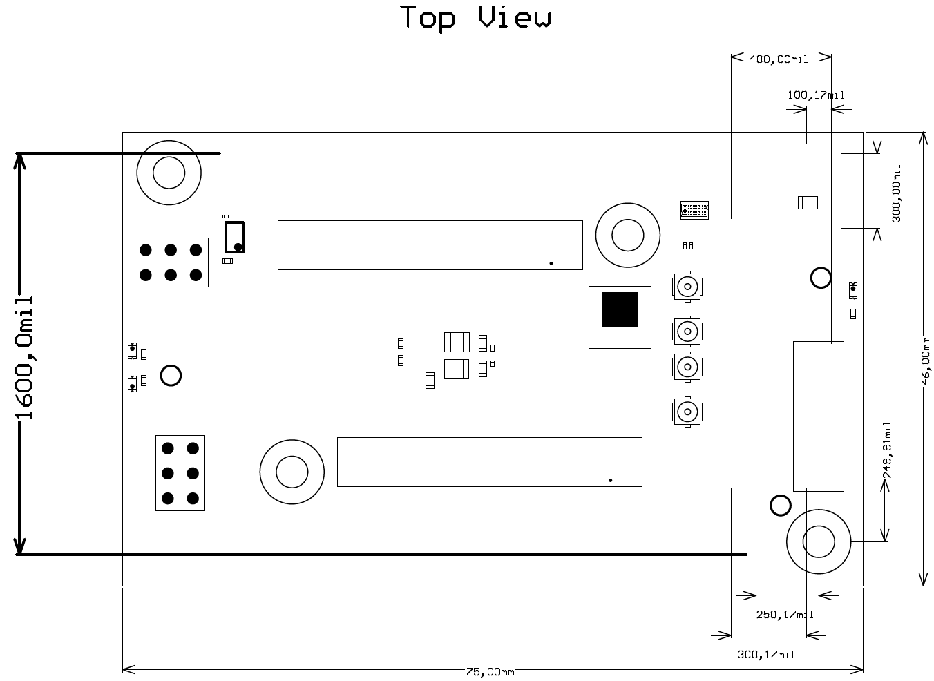
Figure 4: Physical Dimensions of the TEBB0714-01 carrier board
...
Board operating temperature range depends also on customer design and cooling solution. Please contact us for options.
Weight
ca. 32 25 g - Plain board
Document Change History
| date | revision | authors | description |
|---|---|---|---|
| 2017-02-0820 | Ali Naseri | current TRM for TEBB0714-01 | |
| 2017-01-30 | 0.1 | Ali Naseri | Initial document |
...
| Date | Revision | Notes | PCN | Documentation link |
|---|---|---|---|---|
| - | 01 |
|
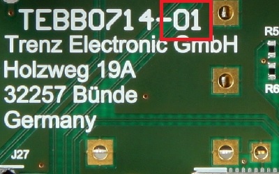
Figure 5: Hardware revision Number
...
Overview
Content Tools