Page History
...
The Trenz Electronic TE0706 carrier board provides functionality for testing, evaluation and development purposes of company's 4 x 5 cm SoMs (System on Module). The Carrier board Board is equipped with various components and connectors for different configuration setups and needs. On-module The interfaces of the SoM's functional components and multipurpose I/Os of the SoM's PL logic are connected via board-to-board connectors to the carrier boardCarrier Board's components and connectors for easy user access.
See "4 x 5 cm carriers" page for more information about supported 4 x 5 cm SoMs.
...
- 5V power connector jack, J1
- Reset switch, S2
- USB type A receptacle, J7
- Micro SD card socket with Card Detect, J4
- 50 pin IDC male connector, J5
- 1000Base-T Gigabit RJ45 Ethernet MagJack, J3
- 1000Base-T Gigabit RJ45 Ethernet MagJack, J2
- JTAG/UART Connectorconnector, JX1
- User DIP switch block, S1
- VCCIO VCCO voltage selection jumper block, J10 - J12
- External connector (VG96) placeholder, J6
- Samtec Razor Beam™ LSHM-150 B2B connector, JB1
- Samtec Razor Beam™ LSHM-150 B2B connector, JB2
- Samtec Razor Beam™ LSHM-130 B2B connector, JB3
...
| PHY | B2B-pin | Notes |
|---|---|---|
| MDC/MDIO | JB3-49, JB3-51 | - |
| LED0 | - | Connected to Ethernet jack J2 LED0 (green). |
| LED1 | - | Connected to Ethernet jack J2 LED1 (green). |
| INT | JB3-33 | - |
| CONFIG | JB3-60 | - |
| RESET | JB3-53 | - |
| RGMII | JB3-37 - JB-44, JB3-47, JB3-57 - JB-59 | Reduced Gigabit Media Independent Interface. 12 pins. |
| SGMII | - | Serial Gigabit Media Independent Interface. Not connected. |
| MDI | - | Media Dependent Interface. Connected to Gigabit-Ethernet MagJack J2. |
RJ45 Gigabit Ethernet MagJack J3
...
| Info |
|---|
| Note: Pin OTG-ID is only assigned to USB 2.0 type B socket. |
DIP switch S1
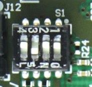
| Switch | Signal Name | ON | OFF | Notes |
|---|---|---|---|---|
| S1-1 | - | - | - | Not connected. |
| S1-2 | PROGMODE | JTAG enabled for programing mounted SoM's Zynq-SoC. | JTAG enabled for programing programing mounted SoM's CPLDs SC-CPLD. | - |
| S1-3 | MODE | Drive SoM SC CPLD pin 'MODE' low. | Leave SoM SC CPLD pin 'MODE' open. | Boot mode configuration, if supported by SoM. (Depends also on SoM's SC-CPLD firmware). |
| S1-4 | EN1 | Drive SoM SC CPLD pin 'EN1' low. | Drive SoM SC CPLD pin 'EN1' high. | Usually used to enable/disable FPGA core-voltage supply. (Depends also on SoM's SC CPLD firmware). Note: Power-on sequence will be intermitted when if S1-4 is set to OFF and if functionality is supported by SoM. |
...
| Note |
|---|
Note: The corresponding PL I/O bank supply-voltages of the 4 x 5 SoM to the selectable base-board voltages VCCIOA, VCCIOB and VCCIOC are depending on the mounted 4 x 5 SoM and varying in order of the used model. Refer to the SoM's schematic for information about the specific pin assignments on module's B2B-connectors regarding the PL I/O bank supply-voltages and to the 4 x 5 Module integration Guide for VCCIO voltage options. |
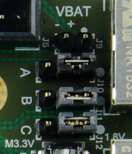
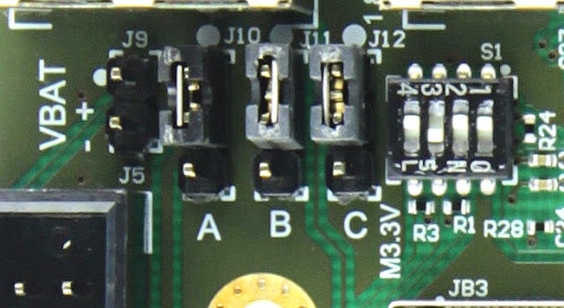
Base-board supply-voltages (VCCIOA, VCCIOB, VCCIOC) selection-jumpers.
...
| Date | Revision | Notes | PCN | Documents |
|---|---|---|---|---|
| 2016-06-28 | 02 | First production revision | - | |
- | 01 | Prototypes | - |
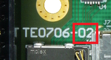
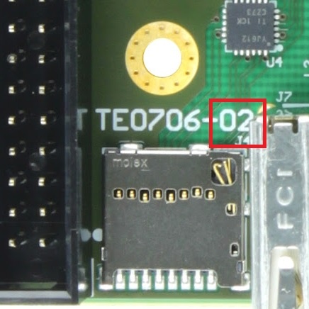
Hardware revision number is printed on the PCB board next to the module model number separated by the dash.
...
Overview
Content Tools