Page History
...
Figure 1: TEBB0714 -01 Block Diagram
Main Components
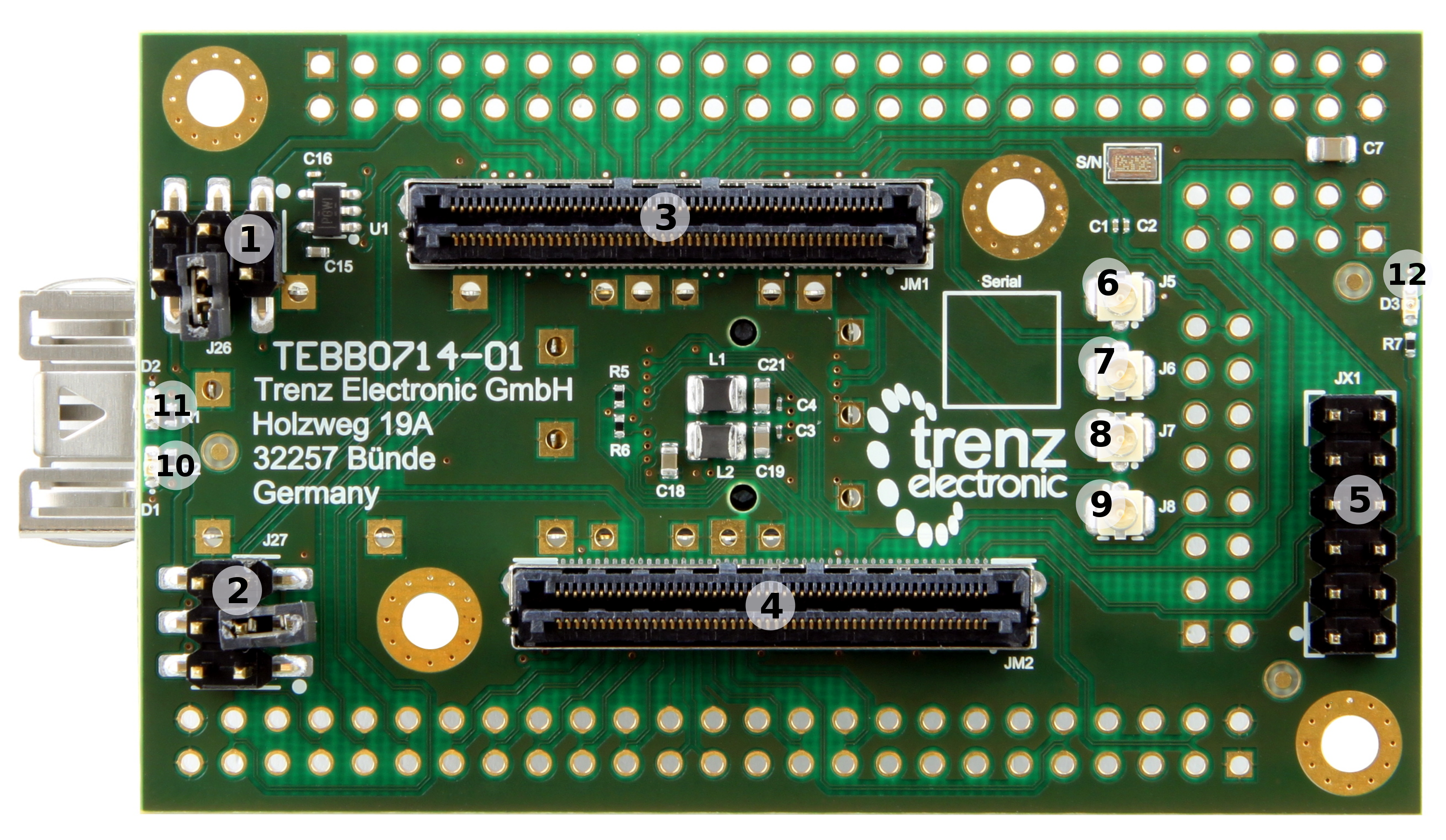
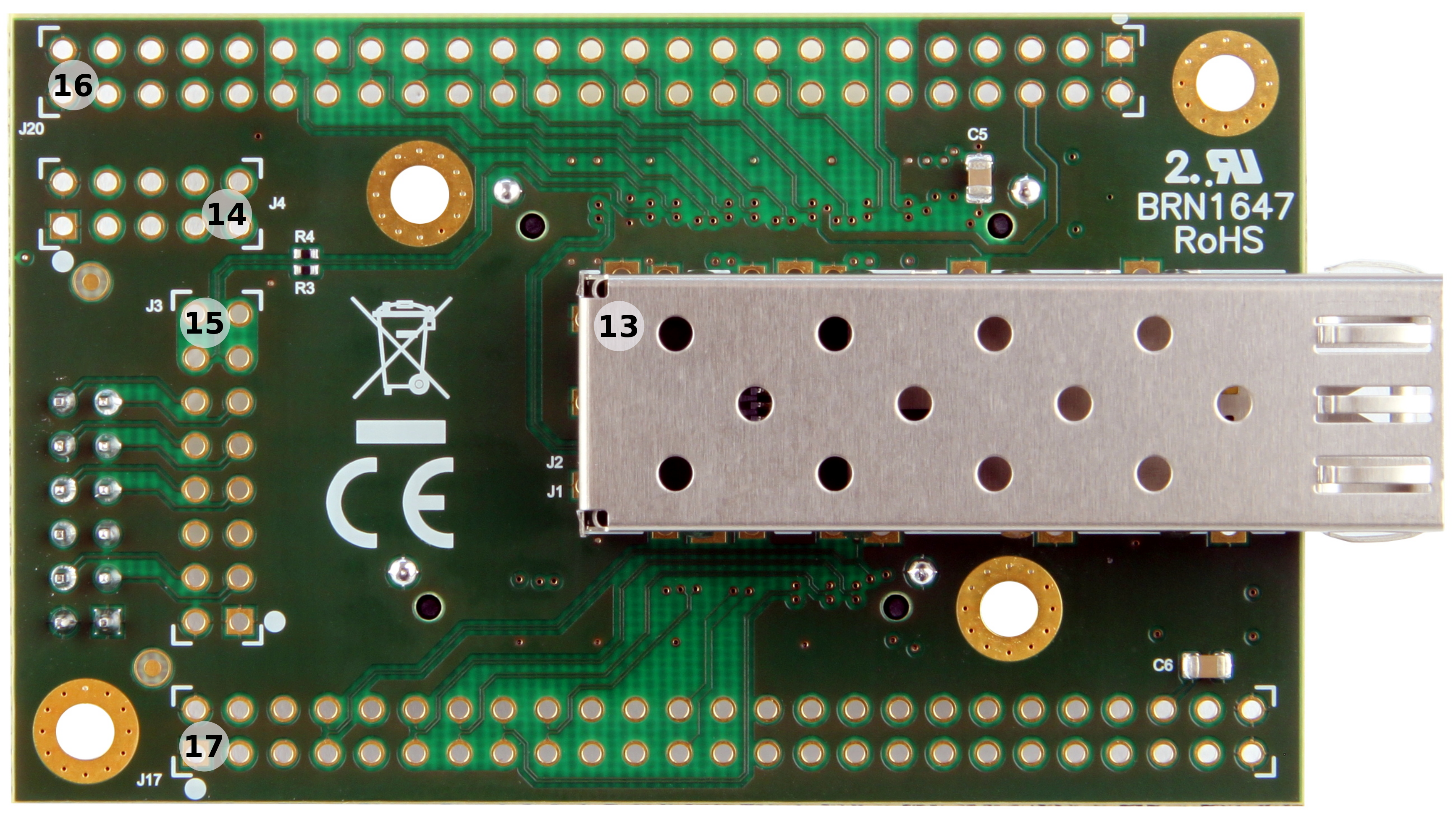
Figure 2: 4 x 5 cm SoM carrier board TEBB0714-01
...
| Note |
|---|
Take care of the VCCO voltage ranges of the particular PL IO-banks (HR, HP) of the mounted SoM, otherwise damages may occur to the FPGA. Therefore, refer to the TRM of the mounted SoM to get the specific information of the voltage ranges. It is recommended to set and measure the PL IO-bank supply-voltages before mounting of TE 4x5 module to avoid failures and damages to the functionality of the mounted SoM. |
Technical Specifications
Absolute Maximum Ratings
...
The dimensions are given in mm and mil (milli inch).
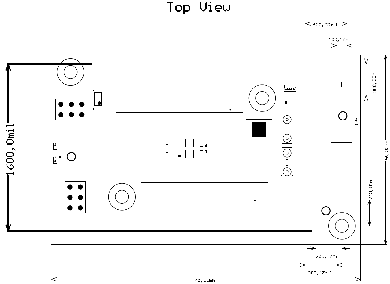
Figure 4: Physical Dimensions of the TEBB0714-01 carrier board
...
Overview
Content Tools