Page History
...
| PMOD | Interface | Connected with | Notes |
|---|---|---|---|
| P1 | GPIO | HP Bank 65 of MPSoC (4 I/O's, B65_T0 ... B65_T3), System Controller CPLD U17 U17 (4 I/O's, EX_IO1 ... EX_IO4) | Voltage translation via IC U33 with direction control, only singled-ended signaling possible |
| P2 | I²C | 8-channel I²C Switch U27 | Accessible on MPSoC's I²C interface through I²C switch U27 |
| P3 | I²C | 8-channel I²C Switch U27 | Accessible on MPSoC's I²C interface through I²C switch U27 |
Table 7: PMOD Pin Assignment
...
Figure 6: TEBF0808 CAN Interfaces, PMOD
Intel PC Compatible Headers and FAN
...
Connectors
The TEBF0808 carrier board provides with its Mini-ITX form factor the possibility to encase the board in a PC Enclosure. For this purpose, the board is equipped with several Intel PC compatible headers to connect them to the PC Enclosure.
...
- Reset Button
- Power Button
- Power LED
- Hard Disc (HD) LED
- Intel High Definition Audio (HDA) Jacks
Following table gives an overview about the particular pins of the headers and a description about their functionalities:
| Header | Pin Name | Function | Connected to | Notes |
|---|---|---|---|---|
| J10 | Pin 1, HD LED+ | HD LED Anode | SC CPLD U39 | also connected to switch button S1 also connected to switch button S2 |
| J9 | Pin 1, PORT1L | Microphone Jack Left Microphone Jack Right Audio Out Jack Left Audio Out Jack Right Jack Detect / Mic in Ground | 24-bit Audio Codec IC U3 | - |
| J23 | Pin 1, 3V3SB Pin 4, S1 | 3.3V DC Supply PC compatible Beeper | SC CPLD U39 | - |
| J26 | Pin 1, GND | Ground 12V DC Supply RPM PWM | SC CPLD U39 | 4-wire PWM FAN connector |
| J35 | Pin 1, GND | Ground 12V DC Supply RPM PWM | SC CPLD U39 | 4-wire PWM FAN connector |
| J19 | Pin 1, GND | Ground 5V DC Supply | Load Switch Q3 (5V DCDC) | 2-wire FAN connector Fan off/on switchable by signal 'FAN_FMC_EN' on SC CPLD U39 |
Table 8: PC compatible Headers
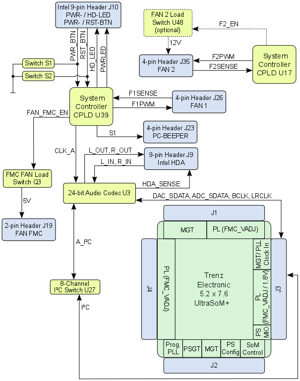
Figure 7: TEBF0808 PC Compatible Headers
...
The System Controller CPLDs will be programmed by the XMOD-Header J28 with cascaded JTAG chain as visualized in Figure 8. To program the System Controller CPLDs, the JTAG interface of these devices have to be activated by DIP-switch S4-3.
The 4 GPIO/UART pins of the XMOD-(XMOD1_A/B/E/G) of the XMOD-Header J28 are routed to the System Controller CPLD U17.
XMOD-Header J12 is designated to program the Zynq Ultrascale+ MPSoC via USB interface, the 4 GPIO/UART pins (XMOD2_A/B/E/G) of this header are routed to the System Controller CPLD U39.
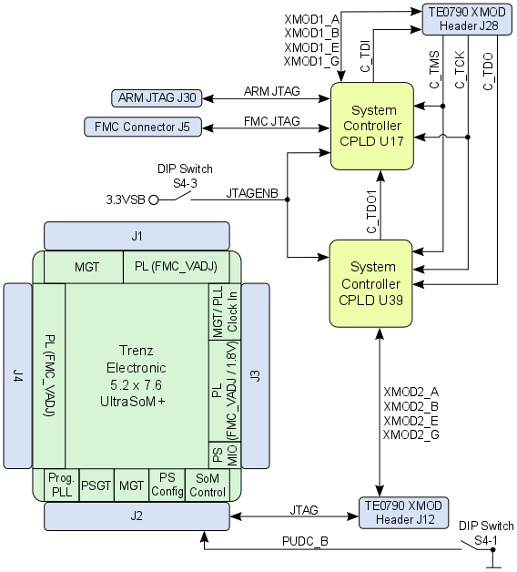
Figure 8: TEBF0808 JTAG interfaces
Further JTAG interfaces of the TEBF0808 carrier board are the ARM JTAG 20-pin IDC connector J30 and on the FMC Connector J5. This JTAG interfaces are connected to the System Controller CPLD U17, hence the logical processing and forwarding of the JTAG signals depend on the SC CPLD firmware. The documentation of the SC CPLD U17 contains detailed information on this matter.
On-board Peripherals
Overview
Content Tools