Page History
...
| Header | Pin Name | Function | Connected to | Notes |
|---|---|---|---|---|
| J10 | Pin 1, HD LED+ | HD LED Anode | SC CPLD U39 | Reset und Power Switch-pins are also connected to switch button S1 also connected to switch button buttons S1 and S2 |
| J9 | Pin 1, PORT1L | Microphone Jack Left Microphone Jack Right Audio Out Jack Left Audio Out Jack Right Jack Detect / Mic in Ground | 24-bit Audio Codec IC U3 | - |
| J23 | Pin 1, 3V3SB Pin 4, S1 | 3.3V DC Supply PC compatible Beeper | SC CPLD U39 | - |
| J26 | Pin 1, GND | Ground 12V DC Supply RPM PWM | SC CPLD U39 | 4-wire PWM FAN connector |
| J35 | Pin 1, GND | Ground 12V DC Supply RPM PWM | SC CPLD U39 | 4-wire PWM FAN connector |
| J19 | Pin 1, GND | Ground 5V DC Supply | Load Switch Q3 (5V DCDC) | 2-wire FAN connector Fan off/on switchable by signal 'FAN_FMC_EN' on SC CPLD U39 |
...
Further JTAG interfaces of the TEBF0808 carrier board are the ARM JTAG 20-pin IDC connector J30 and on the FMC Connector J5. This JTAG interfaces are connected to the System Controller CPLD U17, hence the logical processing and forwarding of the JTAG signals depend on the SC CPLD firmware. The documentation of the SC CPLD U17 contains detailed information on this matter.
On-board Peripherals
System Controller CPDLs
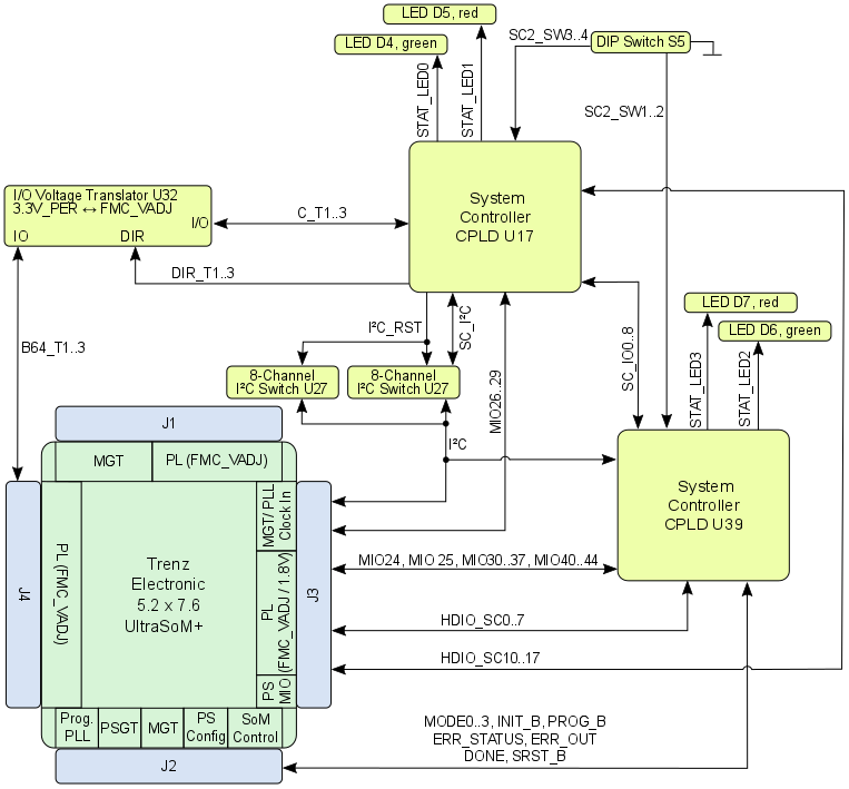
The TEBF0808 is equipped with two System Controller CPLDs with the schematic designators U17 and U39. The CPLDs are provided by Lattice Semiconductor LCMXO2-1200HC (MachXO2 Product Family).
The SC-CPLD is the central system management unit where essential control signals are logically linked by the implemented logic in CPLD firmware, which generates output signals to control the system, the on-board peripherals and the interfaces. Interfaces like JTAG and I2C between the on-board peripherals and to the FPGA-module are by-passed, forwarded and controlled by the System Controller CPLD.
Other tasks of the System Controller CPLD are the monitoring of the power-on sequence and to display the programming state of the FPGA module.
Power and Power-up Sequence
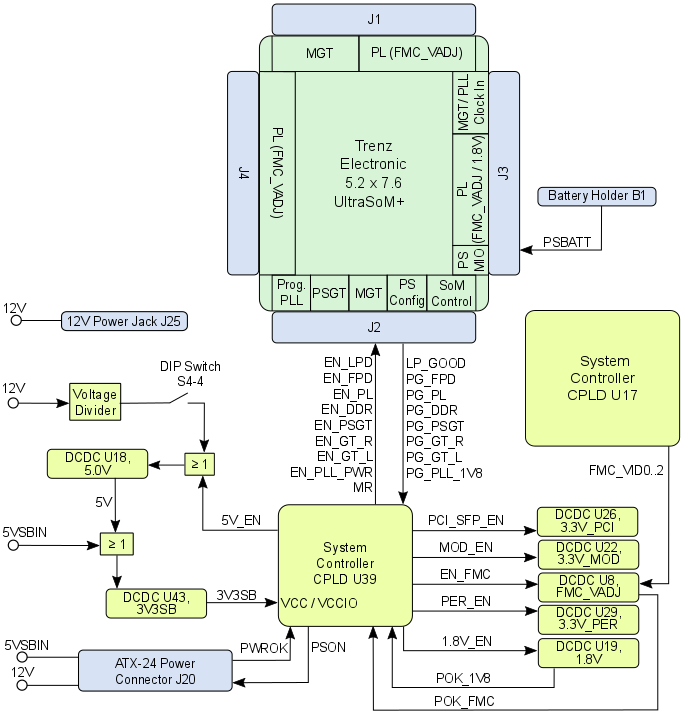
Overview
Content Tools