Page History
...
- Xilinx Zynq UltraScale+ MPSoC 784-pin package (ZU3EG, option for ZU5EV)
- Dual Cortex-A53 64-bit ARM v8 application processing unit (APU)
- Dual Cortex-R5 32-bit ARM v7 real-time processing unit (RPU)
Four high-speed serial I/O (HSSIO) interfaces supporting following protocols:
- PCI Express® interface version 2.1 compliant
- SATA 3.1 specification compliant interface
DisplayPort source-only interface with video resolution up to 4k x 2k
- USB 3.0 specification compliant interface implementing a 5 GbGbit/s line rate
- 1 GbGB/s serial GMII interface
- 132 x HP PL I/Os (3 banks)
- 14 x PS MIOs (6 of the MIOs intended for SD card interface in default configuration)
- 4 x serial PS GTR transceivers
- 32-Bit DDR4, 4 GByte maximum
- Dual parallel SPI boot Flash, 512 MByte maximum
- 4 GByte eMMC (up to 64 GByte)
- GT reference clock input
- PLL for GT clocks (optional external reference)
- Gigabit Ethernet transceiver PHY (Marvell Alaska 88E1512)
- Hi-speed USB 2.0 ULPI transceiver with full OTG support (Microchip USB3320C)
- Programmable quad clock generator
- Plug-on module with 2 x 100-pin and 1 x 60-pin high-speed hermaphroditic strips
- All power supplies on board
- Size: 50 x 40 mm
...
| Storage Device Name | Content | Notes |
|---|---|---|
SPI Flash OTP Area | Empty, not programmed | Except serial number programmed by flash vendor. |
SPI Flash Quad Enable bit | Programmed | - |
SPI Flash main array | Demo design | - |
eFUSE USER | Not programmed | - |
eFUSE Security | Not programmed | - |
| Si5338 OTP NVM | Default settings pre-programmed | OTP not re-programmable after delivery from factory |
Boot Process
Trenz Electronic provides currently 2 Firmware variants, one for SD and one for QSPI usage. At the moment JTAG Mode is needed to write QSPI Flash with Xilinx Tools.
Two different firmware versions are available, one with the QSPI option and other with the SD Card option.
| B2B JM1 MODE Pin | QSPI Firmware Version | SD Card Firmware Version |
|---|---|---|
| Low | ||
| Mode | QSPI-Variant | SD-Variant |
| JTAG | Boot from SD | |
| High | Boot from Flash | JTAG |
For more information read also refer to the TE0820 CPLD - BootMode section.
...
Pin 89 JTAGEN of B2B connector JM1 is used to control which device is accessible via JTAG. If set to low or grounded, JTAG is interface will be routed to the Xilinx Zynq MPSoC. If pulled high, JTAG is interface will be routed to the System Controller CPLD.
| Page break |
|---|
...
| Date | Revision | Notes | PCN Link | Documentation Link |
|---|---|---|---|---|
| 2017-08-17 | 02 | -- | TE0820-02 | |
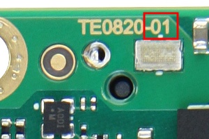
| 2016-12-23 | 01 | Prototyp Prototype only | TE0820-01 |
Hardware revision number is written on the PCB board next to the module model number separated by the dash.
Document Change History
...
| HTML |
|---|
<!-- Generate new entry: 1.add new row below first 2.Copy "Page Information Macro(date)" Macro-Preview, Metadata Version number, Author Name and description to the empty row. Important Revision number must be the same as the Wiki document revision number 3.Update Metadata = "Page Information Macro (current-version)" Preview+1 and add Author and change description. --> |
...
Date | Revision | Contributors | Description | ||||||||
|---|---|---|---|---|---|---|---|---|---|---|---|
| John Hartfiel |
| |||||||||
2017-08-07 | v.5 | Jan Kumann | Initial version. | ||||||||
all | Jan Kumann, John Hartfiel |
...
Overview
Content Tools