...
| HTML |
|---|
<!--
Wiki Link: Go to Base Folder of the Module or Carrier, for example : https://wiki.trenz-electronic.de/display/PD/TE0712
--> |
| Scroll Only (inline) |
|---|
Refer to httpshttp://wiki.trenz-electronic.de/display/PD/<name>org/tem0002-info for the current online version of this manual and other available documentation.
|
The Trenz Electronic TEM0002-01 SmartBerry with Raspberry Pi form factor, is an industrial-grade module based on Microsemi SmartFusion2 SoC (System on a Chip). The Module has 128MB DDR3 SDRAM, a Gigabit Ethernet PHY, four Pmods, a GPIO Pin header compatible to the Raspberry Pi pinout and a Micro USB to UART interface. SmartFusion2 combines a 166 MHz Cortex-M3 core with 256 KByte Flash, 80 KByte SRAM and a 12 kLUT FPGA core logic.
...
- Microsemi SmartFusion2 SoC FPGA (M2S010)
- 128 MByte DDR3 SDRAM
- On board power converters for all needed voltages
- 40 pin header (compatible to Raspberry Pi pinout)
- 4 x 12 pin Pmods
- Gigabit Ethernet PHY with RGMII interface
- JTAG and UART via Micro USB
- 3 pin header for Live Probes
- 2 x User Button
- 2 x status LED
1 x RGB LED
Additional assembly options are available for cost or performance optimization upon request.
Block Diagram
| Scroll Title |
|---|
| anchor | BD_TEM0002 |
|---|
| title | Figure 1: TEM0002-01 block diagram. |
|---|
|
| Scroll Ignore |
|---|
| draw.io Diagram |
|---|
| border | false |
|---|
| viewerToolbar | true |
|---|
| |
|---|
| fitWindow | false |
|---|
| diagramName | BD_TEM0002-01 |
|---|
| simpleViewer | true |
|---|
| width | |
|---|
| links | auto |
|---|
| tbstyle | top |
|---|
| lbox | true |
|---|
| diagramWidth | 641 |
|---|
| revision | 16 |
|---|
|
|
|
...
| Scroll Only |
|---|
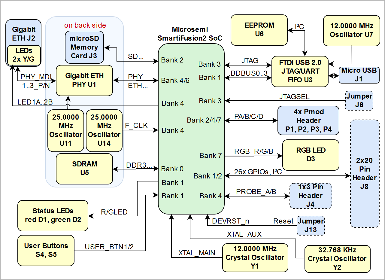 Image Added Image Added
|
|
Main Components
| Scroll Title |
|---|
| anchor | MC_TEM0002 |
|---|
| title | Figure 2: TEM0002-01 |
|---|
|
...
...
| Scroll Ignore |
|---|
| draw.io Diagram |
|---|
| border | false |
|---|
| viewerToolbar | true |
|---|
| |
|---|
| fitWindow | false |
|---|
| diagramName | TEM0002_top_numbered |
|---|
| simpleViewer | true |
|---|
| width |
|---|
|
|
|
...
| 600 | | links | auto |
|---|
| tbstyle | top |
|---|
| lbox | true |
|---|
| diagramWidth | 641 |
|---|
| revision | 8 |
|---|
|
| draw.io Diagram |
|---|
| border | false |
|---|
| viewerToolbar | true |
|---|
| |
|---|
| fitWindow | false |
|---|
| diagramName | TEM0002_bottom_numbered |
|---|
| simpleViewer | true |
|---|
| width |
|---|
|
|
|
...
| 600 | | links | auto |
|---|
| tbstyle | top |
|---|
| lbox | true |
|---|
| diagramWidth | 641 |
|---|
| revision |
|---|
|
|
|
...
| Scroll Only |
|---|
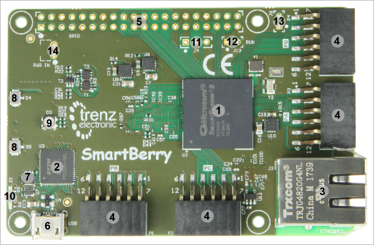 Image Added Image Added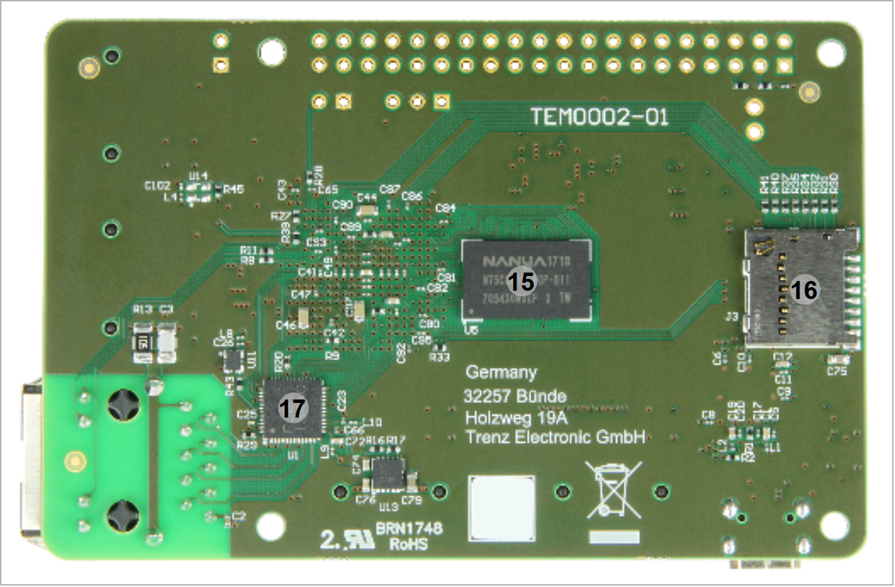 Image Added Image Added
|
|
- Microsemi SmartFusion2 SoC FPGA, U2
- USB to UART/FIFO (FTDI FT2232H), U3
- Gigabit ETH connector, J2
- 4x 2x6 pin Pmod, P1, P2, P3, P4
- GPIO pin header compatible to Raspberry Pi, J8
- Micro USB 2.0, J1
- EEPROM 4KBIT (M93C66-R), U6
- 2x User Button, S4, S5
- RGB LED, D3
- LED red, D1 and green, D2
- Live Probe pins, J4
- Reset jumper, J13
- JTAG select jumper, J6
- Board power header, J5
- 1Gb DDR3/L SDRAM, U5
- MicroSD memory card connector, J3
- Gigabit Ethernet PHY, U1
...
Power Distribution Dependencies
| Scroll Title |
|---|
| anchor | BD_TEM0002 |
|---|
| title | Figure 3: Module power distribution diagram. |
|---|
|
| Scroll Ignore |
|---|
| draw.io Diagram |
|---|
| border | false |
|---|
| viewerToolbar | true |
|---|
| |
|---|
| fitWindow | false |
|---|
| diagramName | PD_TEM0002-01 |
|---|
| simpleViewer | true |
|---|
| width | |
|---|
| links | auto |
|---|
| tbstyle | top |
|---|
| lbox | true |
|---|
| diagramWidth |
|---|
|
|
|
...
...
| Scroll Only |
|---|
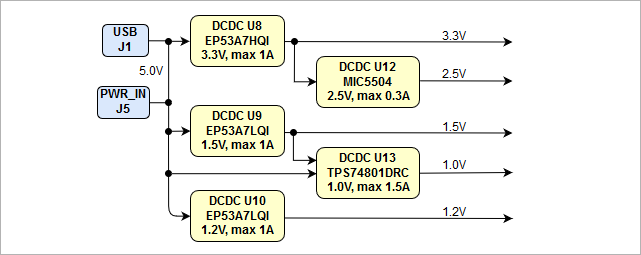 Image Added Image Added
|
|
Power Rails
Power Rail Name | Connector pin | Direction | Notes |
|---|
| VIN | J5-1 | Input | Main supply voltage. |
| 5V | J8-2, J8-4 | Output |
|
| 3.3V | J8-1, J8-17 | Output |
|
| 1.5V | - | Output |
|
1.2V | - | Output |
|
| GND | J5-2, J8-9/25/39/6/14/20/30/34 |
|
|
...
All dimensions are given in millimeters.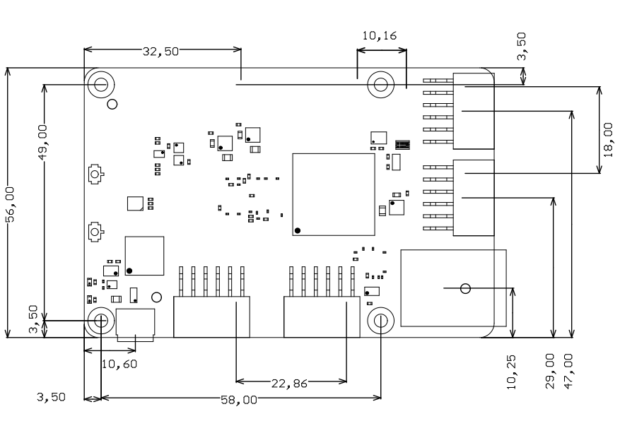 Image Removed
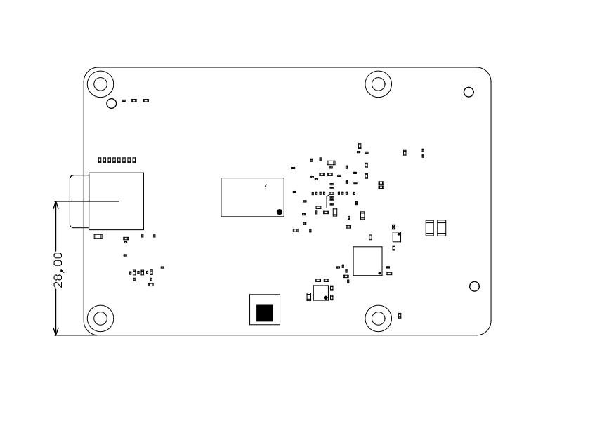 Image Removed
| Scroll Title |
|---|
| anchor | TD_TEM0002 |
|---|
| title | Figure 4: Module physical dimensions drawing. |
|---|
|
Image Added Image Added |
Revision History
Hardware Revision History
...