Page History
...
| HTML |
|---|
<!-- General Design description --> |
Example show, how to reconfigure SI5338 with MCS. Additional Microblaze is add for Hello TE0741 example.
Key Features
| HTML |
|---|
<!-- Add Basic Key Features of the design (should be tested) --> |
...
| Additional Hardware | Notes |
|---|---|
| USB Cable for JTAG/UART | Check Carrier Board and Programmer for correct typtype |
| XMOD Programmer | Carrier Board dependent, only if carrier has no own FTDI |
...
File | File-Extension | Description | |||
|---|---|---|---|---|---|
| BIT-File | *.bit | FPGA (PL Part) Configuration File | |||
| DebugProbes-File | *.ltx | Definition File for Vivado/Vivado Labtools Debugging Interface | |||
| Diverse Reports | --- | Report files in different formats | |||
| Hardware-Platform-Specification-Files | *.hdf | Exported Vivado Hardware Specification for SDK/HSI and PetaLinux | |||
| LabTools Project-File | *.lpr | Vivado Labtools Project File | |||
MCS-File | *.mcs | Flash Configuration File with Boot-Image (MicroBlaze or FPGA part only) | |||
MMI-File | *.mmi | File with BRAM-Location to generate MCS or BIT-File with *.elf content (MicroBlaze only) | OS-Image | *.ub | Image with Linux Kernel (On Petalinux optional with Devicetree and RAM-Disk) |
| Software-Application-File | *.elf | Software Application for Zynq or MicroBlaze Processor SystemsSREC-File | *.srec | Converted Software Application for MicroBlaze Processor Systems |
Download
Reference Design is only usable with the specified Vivado/SDK/PetaLinux/SDx version. Do never use different Versions of Xilinx Software for the same Project.
...
Reference Design is available on:
Design Flow
| HTML |
|---|
<!-- Basic Design Steps Add/ Remove project specific --> |
...
- _create_win_setup.cmd/_create_linux_setup.sh and follow instructions on shell:
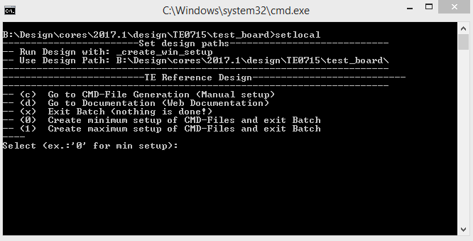
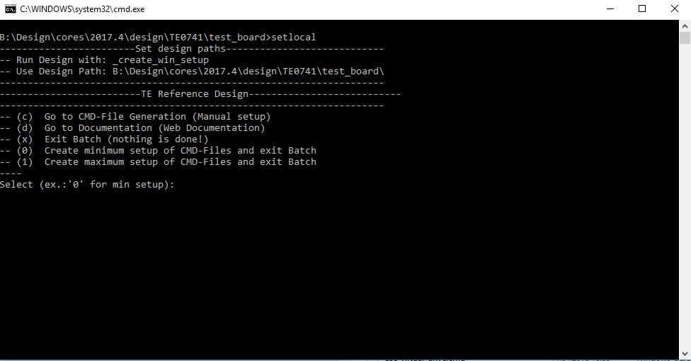
- Press 0 and enter for minimum setup
- (optional Win OS) Generate Virtual Drive or use short directory for the reference design (for example x:\<design name>)
- Create Project
- Select correct device and Xilinx install path on "design_basic_settings.cmd" and create Vivado project with "vivado_create_project_guimode.cmd"
Note: Select correct one, see TE Board Part Files
- Select correct device and Xilinx install path on "design_basic_settings.cmd" and create Vivado project with "vivado_create_project_guimode.cmd"
- Create HDF and export to prebuilt folder
- Run on Vivado TCL: TE::hw_build_design -export_prebuilt
Note: Script generate design and export files into \prebuilt\hardware\<short dir>. Use GUI is the same, except file export to prebuilt folder
- Run on Vivado TCL: TE::hw_build_design -export_prebuilt
- Create Linux (uboot.elf and image.ub) with exported HDF
- HDF is exported to "prebuilt\hardware\<short name>"
Note: HW Export from Vivado GUI create another path as default workspace. - Create Linux images on VM, see PetaLinux KICKstart
- Use TE Template from /os/petalinux
Note: run init_config.sh before you start petalinux config. This will set correct temporary path variable.
Important Note: Select correct Flash partition offset on petalinux-config: Subsystem Auto HW Settings → Flash Settings, FPGA+Boot+bootenv=0x900000 (increase automatically generate Boot partition)
- Use TE Template from /os/petalinux
- HDF is exported to "prebuilt\hardware\<short name>"
- Add Linux files (uboot.elf and image.ub) to prebuilt folder
- "prebuilt\os\petalinux\default" or "prebuilt\os\petalinux\<short name>"
Notes: Scripts select "prebuilt\os\petalinux\<short name>", if exist, otherwise "prebuilt\os\petalinux\default"
- "prebuilt\os\petalinux\default" or "prebuilt\os\petalinux\<short name>"
- Generate UBoot SREC:
- Create SDK Project with TE Scripts on Vivado TCL: TE::sw_run_sdk
- Create "uboot-dummy" application
Note: Use Hello World Example - Copy u-boot.elf into "\workspace\sdk\uboot-dummy\Debug"
- Open "uboot-dummy" properties → C/C++ Build → Settings and go into Build Steps Tap.
- Add to Post-build steps: mb-objcopy -O srec u-boot.elf u-boot.srec
- Press Apply or regenerate project
Note: SREC is generated on "\workspace\sdk\uboot-dummy\Debug\u-boot.srec"
- Generate MCS Firmware (optional):
- Create SDK Project with TE Scripts on Vivado TCL: TE::sw_run_sdk
- Create "SCU" application
Note: Select MCS Microblaze and SCU Application - Select Release Built
- Regenerate App
- Generate Programming Files with HSI/SDK
- Run on Vivado TCL: TE::sw_run_hsi
Note: Scripts generate applications and bootable files, which are defined in "sw_lib\apps_list.csv" - (alternative) Start SDK with Vivado GUI or start with TE Scripts on Vivado TCL: TE::sw_run_sdk
Note: See SDK Projects
- Run on Vivado TCL: TE::sw_run_hsi
- Copy "\prebuilt\software\<short name>\srec_spi_bootloader.elf" into "\firmware\microblaze_0\"
- (optional) Copy "\\workspace\sdk\scu\Release\scu.elf" into "\firmware\microblaze_mcs_0\"
- Regenerate Vivado Project or Update Bitfile only with "srec_spi_bootloader.elf" and "scu.elf"
Launch
...
- Generate MCS Firmware (optional):
- Create SDK Project with TE Scripts on Vivado TCL: TE::sw_run_sdk
- Create "SCU" application
Note: Select MCS Microblaze and SCU Application - Select Release Built
- Regenerate App
- Generate Programming Files with HSI/SDK
- Run on Vivado TCL: TE::sw_run_hsi
Note: Scripts generate applications and bootable files, which are defined in "sw_lib\apps_list.csv" - (alternative) Start SDK with Vivado GUI or start with TE Scripts on Vivado TCL: TE::sw_run_sdk
Note: See SDK Projects
- Run on Vivado TCL: TE::sw_run_hsi
- Copy "\prebuilt\software\<short name>\hello_te0741.elf" into "\firmware\microblaze_0\"
- (optional) Copy "\\workspace\sdk\scu\Release\scu.elf" into "\firmware\microblaze_mcs_0\"
- Regenerate Vivado Project or Update Bitfile only with "hello_te0741.elf" and "scu.elf"
Launch
Programming
| HTML |
|---|
<!--
Description of Block Design, Constrains...
BD Pictures from Export...
--> |
| Note |
|---|
Check Module and Carrier TRMs for proper HW configuration before you try any design. |
Xilinx documentation for programming and debugging: Vivado/SDK/SDSoC-Xilinx Software Programming and Debugging
QSPI
- Connect JTAG and power on PCB
- (if not done) Select correct device and Xilinx install path on "design_basic_settings.cmd" and create Vivado project with "vivado_create_project_guimode.cmd" or open with "vivado_open_project_guimode.cmd", if generated.
- Type on Vivado Console: TE::pr_program_flash_mcsfile -swapp u-boot
Note: Alternative use SDK or setup Flash on Vivado manually - Reboot (if not done automatically)
SD
Not used on this Example.
JTAG
Not used on this Example.
Usage
- Prepare HW like described on section Programming
- Connect UART USB (most cases same as JTAG)
- Power on PCB
Note: FPGA Loads Bitfile from Flash,MCS Firmware configure SI5338 and starts Microblaze, Hello TE0741 from Bitfile Firmware will be run on UART console
Todo Picture
Vivado HW Manager:
- Open Vivado HW-Manager and add VIO signal to dashboard (*.ltx located on prebuilt folder).
- Set radix from VIO signals (MGT...) to unsigned integer.
Note: Frequency Counter is inaccurate and displayed unit is Hz - MGT REF~125MHz, MIG_50MHZ~50MHz., CLK1B ~50MHz, CLK0~100MHz
- Additional Infos: System reset from MCS and GIO outputs
- Set radix from VIO signals (MGT...) to unsigned integer.
Todo Picture
System Design - Vivado
| HTML |
|---|
<!-- Description of Block Design, Constrains... BD Pictures from Export... --> |
| Note |
|---|
Check Module and Carrier TRMs for proper HW configuration before you try any design. |
Xilinx documentation for programming and debugging: Vivado/SDK/SDSoC-Xilinx Software Programming and Debugging
QSPI
- Connect JTAG and power on PCB
- (if not done) Select correct device and Xilinx install path on "design_basic_settings.cmd" and create Vivado project with "vivado_create_project_guimode.cmd" or open with "vivado_open_project_guimode.cmd", if generated.
- Type on Vivado Console: TE::pr_program_flash_mcsfile -swapp u-boot
Note: Alternative use SDK or setup Flash on Vivado manually - Reboot (if not done automatically)
SD
Not used on this Example.
JTAG
Not used on this Example.
Usage
- Prepare HW like described on section 43679821
- Connect UART USB (most cases same as JTAG)
- Power on PCB
Note: FPGA Loads Bitfile from Flash,MCS Firmware configure SI5338 and starts Microblaze, SREC Bootloader from Bitfile Firmware loads U-Boot into DDR (This takes a while), U-boot loads Linux from QSPI Flash into DDR
Boot process takes a while, please wait.

Linux
Note: Linux boot process is slower on Microblaze.
- Open Serial Console (e.g. putty)
- Speed: 9600
- COM Port: Win OS, see device manager, Linux OS see dmesg |grep tty (UART is *USB1)
- Linux Console:
Note: Wait until Linux boot finished For Linux Login use:- User Name: root
- Password: root
- You can use Linux shell now.
- ETH0 works with udhcpc
- ETH0 works with udhcpc
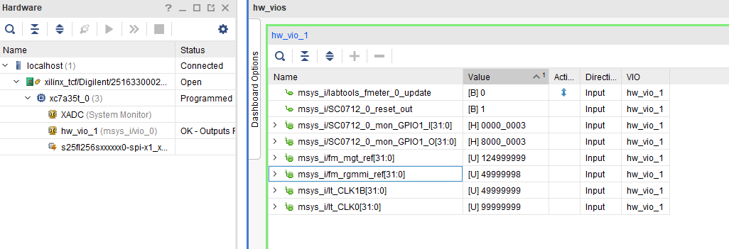
Vivado HW Manager:
- Open Vivado HW-Manager and add VIO signal to dashboard (*.ltx located on prebuilt folder).
- Set radix from VIO signals (MGT REF, MIG_OUT, CLK1B, CLK0) to unsigned integer.
Note: Frequency Counter is inaccurate and displayed unit is Hz - MGT REF~125MHz, MIG_50MHZ~50MHz., CLK1B ~50MHz, CLK0~100MHz
- Additional Infos: System reset from MCS and GIO outputs
- Set radix from VIO signals (MGT REF, MIG_OUT, CLK1B, CLK0) to unsigned integer.
System Design - Vivado
| HTML |
|---|
<!--
Description of Block Design, Constrains...
BD Pictures from Export...
--> |
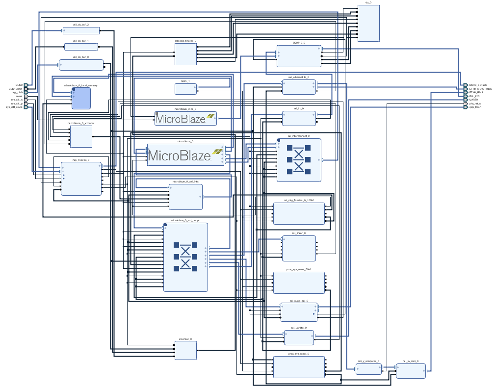
Block Design
Constrains
Basic module constrains
| Code Block | ||||
|---|---|---|---|---|
| ||||
set_property BITSTREAM.GENERAL.COMPRESS TRUE [current_design]
set_property BITSTREAM.CONFIG.CONFIGRATE 66 [current_design]
set_property CONFIG_VOLTAGE 3.3 [current_design]
set_property CFGBVS VCCO [current_design]
set_property CONFIG_MODE SPIx4 [current_design]
set_property BITSTREAM.CONFIG.SPI_32BIT_ADDR YES [current_design]
set_property BITSTREAM.CONFIG.SPI_BUSWIDTH 4 [current_design]
set_property BITSTREAM.CONFIG.M1PIN PULLNONE [current_design]
set_property BITSTREAM.CONFIG.M2PIN PULLNONE [current_design]
set_property BITSTREAM.CONFIG.M0PIN PULLNONE [current_design]

set_property BITSTREAM.CONFIG.USR_ACCESS TIMESTAMP [current_design] |
| Code Block | ||||
|---|---|---|---|---|
| ||||
set_property BITSTREAM.CONFIG.UNUSEDPIN PULLDOWN [current_design] |
Design specific constrain
| Code Block | ||||||||
|---|---|---|---|---|---|---|---|---|
| ||||||||
set_property PULLDOWN true [get_ports reset] |
| Code Block | ||||||||
|---|---|---|---|---|---|---|---|---|
| ||||||||
#I2C
set_property PACKAGE_PIN W21 [get_ports PLL_I2C_scl_io]
set_property IOSTANDARD LVCMOS33 [get_ports PLL_I2C_scl_io]
set_property PACKAGE_PIN T20 [get_ports PLL_I2C_sda_io]
set_property IOSTANDARD LVCMOS33 [get_ports PLL_I2C_sda_io]

#Reset
set_property PACKAGE_PIN T3 [get_ports reset]
set_property IOSTANDARD LVCMOS15 [get_ports reset]
#CLKS
set_property PACKAGE_PIN R4 [get_ports {CLK1B[0]}]
set_property IOSTANDARD LVCMOS15 [get_ports {CLK1B[0]}]
set_property PACKAGE_PIN K4 [get_ports {CLK0_clk_p[0]}]
set_property IOSTANDARD DIFF_SSTL15 [get_ports {CLK0_clk_p[0]}]

#ETH PHY
set_property PACKAGE_PIN N17 [get_ports phy_rst_n]
set_property IOSTANDARD LVCMOS33 [get_ports phy_rst_n |
| Code Block | ||||||||
|---|---|---|---|---|---|---|---|---|
| ||||||||
create_clock -period 8.000 -name mgt_clk0_clk_p -waveform {0.000 4.000} [get_ports mgt_clk0_clk_p]


create_clock -period 10.000 -name {CLK0_clk_p[0]} -waveform {0.000 5.000} [get_ports {CLK0_clk_p[0]}]
create_clock -period 20.000 -name {CLK1B[0]} -waveform {0.000 10.000} [get_ports {CLK1B[0]}]
create_clock -period 15.152 -name msys_i/axi_quad_spi_0/U0/NO_DUAL_QUAD_MODE.QSPI_NORMAL/QSPI_LEGACY_MD_GEN.QSPI_CORE_INTERFACE_I/LOGIC_FOR_MD_12_GEN.SCK_MISO_STARTUP_USED.QSPI_STARTUP_BLOCK_I/cfgmclk -waveform {0.000 7.576} [get_pins msys_i/axi_quad_spi_0/U0/NO_DUAL_QUAD_MODE.QSPI_NORMAL/QSPI_LEGACY_MD_GEN.QSPI_CORE_INTERFACE_I/LOGIC_FOR_MD_12_GEN.SCK_MISO_STARTUP_USED.QSPI_STARTUP_BLOCK_I/STARTUP_7SERIES_GEN.STARTUP2_7SERIES_inst/CFGMCLK]


set_false_path -from [get_clocks {CLK0_clk_p[0]}] -to [get_clocks clk_pll_i]
set_false_path -from [get_clocks mgt_clk0_clk_p] -to [get_clocks clk_pll_i]
set_false_path -from [get_clocks msys_i/axi_quad_spi_0/U0/NO_DUAL_QUAD_MODE.QSPI_NORMAL/QSPI_LEGACY_MD_GEN.QSPI_CORE_INTERFACE_I/LOGIC_FOR_MD_12_GEN.SCK_MISO_STARTUP_USED.QSPI_STARTUP_BLOCK_I/cfgmclk] -to [get_clocks clk_pll_i]


set_false_path -from [get_clocks -of_objects [get_pins msys_i/mig_7series_0/u_msys_mig_7series_0_0_mig/u_ddr3_infrastructure/gen_ui_extra_clocks.mmcm_i/CLKFBOUT]] -to [get_clocks mgt_clk0_clk_p]

set_false_path -from [get_clocks clk_pll_i] -to [get_clocks {msys_i/util_ds_buf_0/U0/IBUF_OUT[0]}]
set_false_path -from [get_pins {msys_i/labtools_fmeter_0/U0/F_reg[*]/C}] -to [get_pins {msys_i/vio_0/inst/PROBE_IN_INST/probe_in_reg_reg[*]/D}]
set_false_path -from [get_pins msys_i/labtools_fmeter_0/U0/COUNTER_REFCLK_inst/bl.DSP48E_2/CLK] -to [get_pins {msys_i/vio_0/inst/PROBE_IN_INST/probe_in_reg_reg[*]/D}]
set_false_path -from [get_pins {msys_i/labtools_fmeter_0/U0/FMETER_gen[*].COUNTER_F_inst/bl.DSP48E_2/CLK}] -to [get_pins {msys_i/labtools_fmeter_0/U0/F_reg[*]/D}]
|
Software Design - SDK/HSI
| HTML |
|---|
<!--
optional chapter
separate sections for different apps
--> |
For SDK project creation, follow instructions from:
Application
SCU
MCS Firmware to configure SI5338 and Reset System.
Template location: \sw_lib\sw_apps\scu
SREC SPI BootLoader
Add some Console outputs and changed Bootloader Read Address.
Template location: \sw_lib\sw_apps\srec_spi_bootloader
xilisf_v5_9
Changed default Flash Typ to 5.
Template location: \sw_lib\sw_services
U-Boot
U-Boot.elf is generated with PetaLinux. SDK/HSI is used to generate u-boot.srec. Vivado to generate *.mcs
Software Design - PetaLinux
| HTML |
|---|
<!--
optional chapter
--> |
Description currently not available.
Config
- Set kernel flash Address to 0x900000 and Kernel size to 0xA00000:
(--> Subsystem Auto Hardware Settings --> Flash Settings)- SUBSYSTEM_FLASH_AXI_QUAD_SPI_0_BANKLESS_PART0_SIZE = 0x5E0000
- SUBSYSTEM_FLASH_AXI_QUAD_SPI_0_BANKLESS_PART1_SIZE = 0x300000
- SUBSYSTEM_FLASH_AXI_QUAD_SPI_0_BANKLESS_PART2_SIZE = 0x20000
- SUBSYSTEM_FLASH_AXI_QUAD_SPI_0_BANKLESS_PART3_SIZE = 0xA00000
U-Boot
| Code Block | ||
|---|---|---|
| ||
#include <configs/platform-auto.h>


#undef CONFIG_PHY_XILINX
#undef XILINX_EMACLITE_BASEADDR    0x40E00000
#undef CONFIG_MII
#undef CONFIG_PHY_GIGE
#undef CONFIG_PHY_MARVELL
#undef CONFIG_PHY_NATSEMI
#undef CONFIG_NET_MULTI
#undef CONFIG_BOOTP_MAY_FAIL
#undef CONFIG_NETCONSOLE    1
#undef CONFIG_SERVERIP    192.168.150.117
#undef CONFIG_IPADDR


/* PREBOOT */
#define CONFIG_PREBOOT    "echo U-BOOT for petalinux;setenv preboot; echo; "
|
Device Tree
| Code Block | ||
|---|---|---|
| ||
/include/ "system-conf.dtsi"
/ {
};

/* ETH PHY */
&axi_ethernetlite_0 {
    phy-handle = <&phy0>;
    mdio {
        #address-cells = <1>;
        #size-cells = <0>;
        phy0: phy@0 {
            device_type = "ethernet-phy";
            reg = <1>;
        };
    };
};
|
Kernel
No changes.
Rootfs
No changes.
Applications
No changes.
Additional Software
| HTML |
|---|
<!--
Add Description for other Software, for example SI CLK Builder ...
--> |
SI5338
Download ClockBuilder Desktop for SI5338
- Install and start ClockBuilder
- Select SI5338
- Options → Open register map file
Note: File location <design name>/misc/Si5338/RegisterMap.txt - Modify settings
- Options → save C code header files
- Replace Header files from FSBL template with generated file
Appx. A: Change History and Legal Notices
Document Change History
To get content of older revision got to "Change History" of this page and select older document revision number.
| HTML |
|---|
<!--
Generate new entry:
1:add new row below first
2:Copy Page Information Macro(date+user) Preview, Page Information Macro Preview
3.Update Metadate =Page Information Macro Preview+1
--> |
Block Design
Todo
Constrains
Basic module constrains
| Code Block | ||||
|---|---|---|---|---|
| ||||
set_property BITSTREAM.GENERAL.COMPRESS TRUE [current_design]
set_property BITSTREAM.CONFIG.CONFIGRATE 66 [current_design]
set_property CONFIG_VOLTAGE 3.3 [current_design]
set_property CFGBVS VCCO [current_design]
set_property CONFIG_MODE SPIx4 [current_design]
set_property BITSTREAM.CONFIG.SPI_32BIT_ADDR YES [current_design]
set_property BITSTREAM.CONFIG.SPI_BUSWIDTH 4 [current_design]
set_property BITSTREAM.CONFIG.M1PIN PULLNONE [current_design]
set_property BITSTREAM.CONFIG.M2PIN PULLNONE [current_design]
set_property BITSTREAM.CONFIG.M0PIN PULLNONE [current_design]

set_property BITSTREAM.CONFIG.USR_ACCESS TIMESTAMP [current_design] |
Design specific constrain
| Code Block | ||||||||
|---|---|---|---|---|---|---|---|---|
| ||||||||
#LED
set_property PACKAGE_PIN D26 [get_ports {LED_D1[0]}]
set_property IOSTANDARD LVCMOS33 [get_ports {LED_D1[0]}]
set_property PACKAGE_PIN E26 [get_ports {LED_D2[0]}]
set_property IOSTANDARD LVCMOS33 [get_ports {LED_D2[0]}]
#MGT Power
set_property PACKAGE_PIN G25 [get_ports {PG_MGT_1V2[0]}]
set_property IOSTANDARD LVCMOS33 [get_ports {PG_MGT_1V2[0]}]
set_property PACKAGE_PIN K23 [get_ports {PG_MGT_1V[0]}]
set_property IOSTANDARD LVCMOS33 [get_ports {PG_MGT_1V[0]}]
set_property PACKAGE_PIN H22 [get_ports {EN_MGT[0]}]
set_property IOSTANDARD LVCMOS33 [get_ports {EN_MGT[0]}]
#SI5338 CLK
set_property PACKAGE_PIN C26 [get_ports {CLK_EN[0]}]
set_property IOSTANDARD LVCMOS33 [get_ports {CLK_EN[0]}]
#I2C PLL SI5338
set_property PACKAGE_PIN A20 [get_ports ext_scl_o]
set_property IOSTANDARD LVCMOS33 [get_ports ext_scl_o]
set_property PACKAGE_PIN B21 [get_ports ext_sda]
set_property IOSTANDARD LVCMOS33 [get_ports ext_sda] |
| Code Block | ||||||||
|---|---|---|---|---|---|---|---|---|
| ||||||||
#Fmeter can be ignored, it's only simple measurement

set_false_path -from [get_pins {msys_i/labtools_fmeter_0/U0/FMETER_gen[*].COUNTER_F_inst/bl.DSP48E_2/CLK}] -to [get_pins {msys_i/labtools_fmeter_0/U0/F_reg[*]/D}]

set_false_path -from [get_pins msys_i/labtools_fmeter_0/U0/toggle_reg/C] -to [get_pins {msys_i/labtools_fmeter_0/U0/FMETER_gen[*].COUNTER_F_inst/bl.DSP48E_2/RSTC}]
set_false_path -from [get_pins msys_i/labtools_fmeter_0/U0/toggle_reg/C] -to [get_pins {msys_i/labtools_fmeter_0/U0/FMETER_gen[*].COUNTER_F_inst/bl.DSP48E_2/RSTA}]
set_false_path -from [get_pins msys_i/labtools_fmeter_0/U0/toggle_reg/C] -to [get_pins {msys_i/labtools_fmeter_0/U0/FMETER_gen[*].COUNTER_F_inst/bl.DSP48E_2/RSTB}]
set_false_path -from [get_pins msys_i/labtools_fmeter_0/U0/toggle_reg/C] -to [get_pins {msys_i/labtools_fmeter_0/U0/FMETER_gen[*].COUNTER_F_inst/bl.DSP48E_2/CEALUMODE}]
set_false_path -from [get_pins msys_i/labtools_fmeter_0/U0/toggle_reg/C] -to [get_pins {msys_i/labtools_fmeter_0/U0/FMETER_gen[*].COUNTER_F_inst/bl.DSP48E_2/RSTCTRL}]


set_false_path -from [get_clocks -of_objects [get_pins msys_i/clk_wiz_1/inst/mmcm_adv_inst/CLKOUT0]] -to [get_clocks {msys_i/util_ds_buf_0/U0/IBUF_OUT[0]}]
set_false_path -from [get_clocks -of_objects [get_pins msys_i/clk_wiz_1/inst/mmcm_adv_inst/CLKOUT0]] -to [get_clocks {msys_i/util_ds_buf_1/U0/IBUF_OUT[0]}]
|
Software Design - SDK/HSI
| HTML |
|---|
<!--
optional chapter
separate sections for different apps
--> |
For SDK project creation, follow instructions from:
Application
SCU
MCS Firmware to configure SI5338 and Reset System.
Template location: \sw_lib\sw_apps\scu
Hello TE0741
Xilinx Hello World example as andless loop
Template location: \sw_lib\sw_apps\hello_te0741
Additional Software
| HTML |
|---|
<!--
Add Description for other Software, for example SI CLK Builder ...
--> |
SI5338
Download ClockBuilder Desktop for SI5338
- Install and start ClockBuilder
- Select SI5338
- Options → Open register map file
Note: File location <design name>/misc/Si5338/RegisterMap.txt - Modify settings
- Options → save C code header files
- Replace Header files from SCU template with generated file
Appx. A: Change History and Legal Notices
Document Change History
To get content of older revision got to "Change History" of this page and select older document revision number.
| HTML |
|---|
<!--
Generate new entry:
1:add new row below first
2:Copy Page Information Macro(date+user) Preview, Page Information Macro Preview
3.Update Metadate =Page Information Macro Preview+1
--> |
| Date | Document Revision | Authors | Description | ||||||||||||||||||||||
|---|---|---|---|---|---|---|---|---|---|---|---|---|---|---|---|---|---|---|---|---|---|---|---|---|---|
|
|
|
| ||||||||||||||||||||||
| 2018-04-16 | |||||||||||||||||||||||||
| Date | Document Revision | Authors | Description | ||||||||||||||||||||||
| Page info | modified-date | modified-date | |||||||||||||||||||||||
| dateFormat | yyyy-MM-dd | ||||||||||||||||||||||||
| Page info | current-version | current-version | |||||||||||||||||||||||
| prefix | v. | ||||||||||||||||||||||||
| Page info | modified-user | modified-user |
| ||||||||||||||||||||||
| v.23 | John Hartfiel | Design Update | |||||||||||||||||||||||
| v.22 | John Hartfiel |
| |||||||||||||||||||||||
| 2018-02-13 | v.19 | John Hartfiel |
| ||||||||||||||||||||||
| 2018-01-08 | v.16 | John Hartfiel |
| ||||||||||||||||||||||
| 2017-12-15 | v.15 | John Hartfiel |
| ||||||||||||||||||||||
| 2017-11-07 | v.11 | John Hartfiel |
| ||||||||||||||||||||||
| 2017-10-06 | v.10 | John Hartfiel |
| ||||||||||||||||||||||
| 2017-10-05 | v.8 | John Hartfiel |
| ||||||||||||||||||||||
| 2017-09-11 | v.1 |
|
| ||||||||||||||||||||||
| All |
|
...
Overview
Content Tools