| Page properties |
|---|
|
In this section you must explain how to power on the board and run the Reference Design (test board) on the particular module. The main points must be mentioned are: |
| Scroll pdf ignore |
|---|
Table of Contents |
TEB0728 with TE0728
Overview
| Scroll Title |
|---|
| anchor | Figure_Overview |
|---|
| title | Board Overview |
|---|
|
...
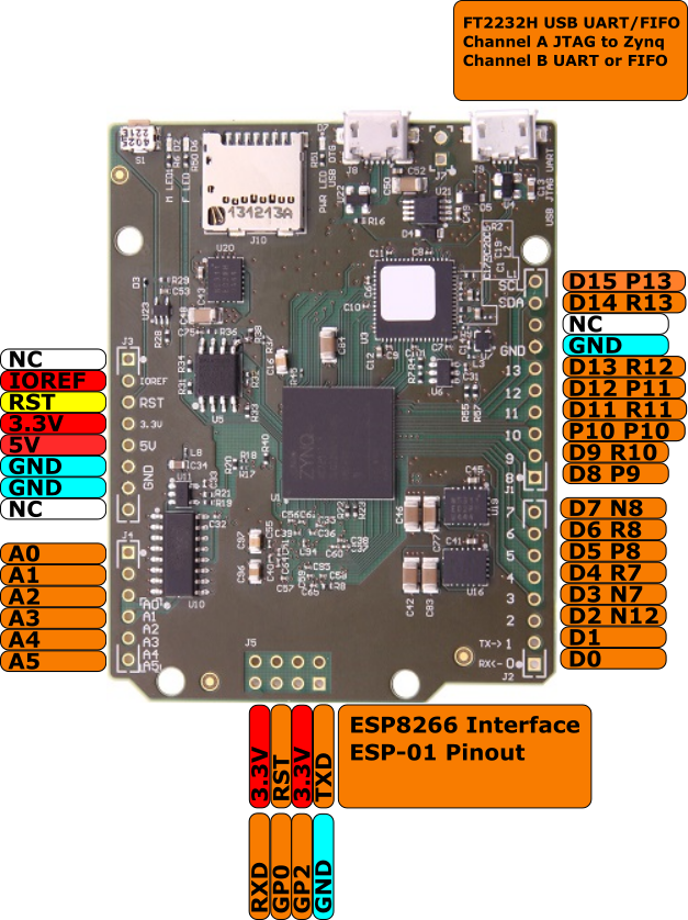 Image Removed
Power supply
Over MicroUSB (5V) possible.
DIP-Switches
|
| Scroll Ignore |
|---|
| scroll-pdf | true |
|---|
| scroll-office | true |
|---|
| scroll-chm | true |
|---|
| scroll-docbook | true |
|---|
| scroll-eclipsehelp | true |
|---|
| scroll-epub | true |
|---|
| scroll-html | true |
|---|
| | draw.io Diagram |
|---|
| border | false |
|---|
| viewerToolbar | true |
|---|
| |
|---|
| fitWindow | false |
|---|
| diagramDisplayName | |
|---|
| lbox | true |
|---|
| revision | 11 |
|---|
| diagramName | TE0728_OV |
|---|
| simpleViewer | false |
|---|
| width | |
|---|
| links | auto |
|---|
| tbstyle | hidden |
|---|
| diagramWidth | 641 |
|---|
|
|
| Scroll Only |
|---|
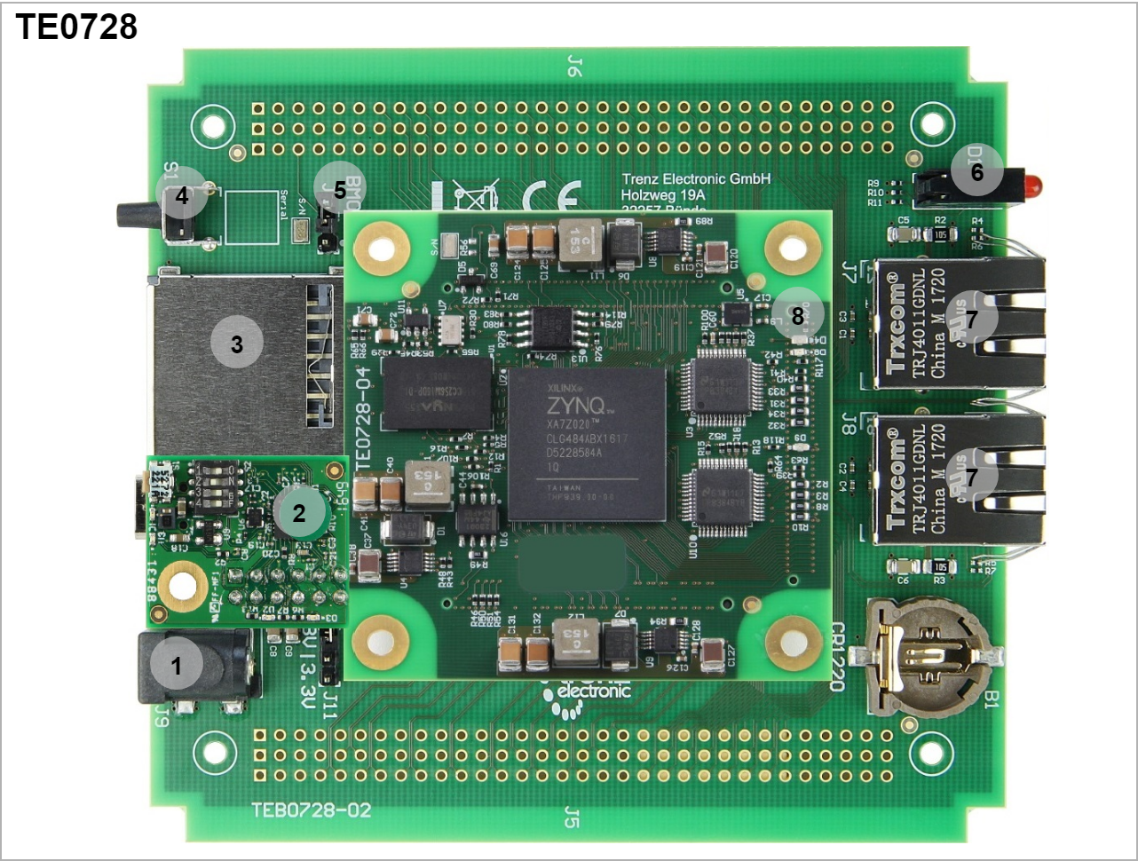 Image Added Image Added
|
|
- Barrel Jack Power Supply
- XMOD JTAG Adapter
- SD card holder
- Reset
- Boot mode Jumper
- Carrier LEDs (Red,Yellow,Green) D1
- Ethernet Socket
- Module LEDs (Green D4, Red D8)
Power supply
| Page properties |
|---|
|
The input power supply must be mentioned. |
Single 5V power supply with minimum current capability of 2.5A is recommended to power on the board.
| Scroll Title |
|---|
| anchor | Table_DIP_PWR |
|---|
| title | Power Supply |
|---|
|
| Scroll Table Layout |
|---|
| orientation | portrait |
|---|
| sortDirection | ASC |
|---|
| repeatTableHeaders | default |
|---|
| style | |
|---|
| widths | |
|---|
| sortByColumn | 1 |
|---|
| sortEnabled | false |
|---|
| cellHighlighting | true |
|---|
|
|
DIP-Switches and Push Buttons
| Page properties |
|---|
|
Explain all DIP switches functionality. |
There is a switch (S1) which is connected to RESET signal, it resets the system entirely.
| Scroll Title |
|---|
| anchor | Table_DIP_PB |
|---|
| title | DIP Switches /Push Buttons |
|---|
|
| Scroll Table Layout |
|---|
| orientation | portrait |
|---|
| sortDirection | ASC |
|---|
| repeatTableHeaders | default |
|---|
| style | |
|---|
| widths | |
|---|
| sortByColumn | 1 |
|---|
| sortEnabled | false |
|---|
| cellHighlighting | true |
|---|
|
Overview 4 | Connected to | B2B | Active Level |
|---|
S1 | RESET | J2-7 | Active High |
|
There is no DIPs on TE0728There are no DIPs on TE0722. In case of TE0790 (XMOD) usage, see power supply section.
LEDs
D2(red): User LED connected to MIO9
D6(green): User LED connected to G14
D7(green): 3.3V Power LED
JTAG/UART
JTAG and UART is possible over miro USB connector.
miroUSB UART is connected to PL IO (RX: Pin H13, TX: Pin H14).
Reference Designs
Notes
DIPs mode.
Jumpers
| Page properties |
|---|
|
Explain all Jumpers functionality and connection. |
| Scroll Title |
|---|
| anchor | Table_Jumpers |
|---|
| title | Jumpers |
|---|
|
| Scroll Table Layout |
|---|
| orientation | portrait |
|---|
| sortDirection | ASC |
|---|
| repeatTableHeaders | default |
|---|
| style | |
|---|
| widths | |
|---|
| sortByColumn | 1 |
|---|
| sortEnabled | false |
|---|
| cellHighlighting | true |
|---|
|
| Overview 5 | Connected to | B2B | Note |
|---|
| J4 | Boot_R | J2-11 | Open: QSPI | | Short: SD Card |
|
LEDs
| Page properties |
|---|
|
Explain all user LEDs functionality and connections. |
There are three user LEDs on the carrier TEB0728 which can be used for variant purposes.
| Scroll Title |
|---|
| anchor | Table_LED |
|---|
| title | Carrier LEDs |
|---|
|
| Scroll Table Layout |
|---|
| orientation | portrait |
|---|
| sortDirection | ASC |
|---|
| repeatTableHeaders | default |
|---|
| style | |
|---|
| widths | |
|---|
| sortByColumn | 1 |
|---|
| sortEnabled | false |
|---|
| cellHighlighting | true |
|---|
|
| Overview 6 | Color | Connected to | B2B | Active Level | Note |
|---|
| D1-A | Red | MIO48 | J2-30 | Active high | User LED | | D1-B | Yellow | MIO49 | J2-38 | Active high | User LED | | D1-C | Green | MIO50 | J2-36 | Active high | User LED |
|
Furthermore, there are two user LEDs on module TE0728.
| Scroll Title |
|---|
| anchor | Table_LED |
|---|
| title | Module LEDs |
|---|
|
| Scroll Table Layout |
|---|
| orientation | portrait |
|---|
| sortDirection | ASC |
|---|
| repeatTableHeaders | default |
|---|
| style | |
|---|
| widths | |
|---|
| sortByColumn | 1 |
|---|
| sortEnabled | false |
|---|
| cellHighlighting | true |
|---|
|
| Overview 8 | Color | Connected to | B2B | Active Level | Note |
|---|
| D4 | Green | Bank33 pin V18 | - | Active high | User LED | | D9 | Green | DONE_0 |
|
| DONE pin | | D8 | Red | MIO7 | - | Active high | User LED |
|
JTAG/UART
| Page properties |
|---|
|
Explain JTAG or UART connection breifly. |
JTAG and UART connections are available through XMOD JTAG adapter. For more information refer to TE0790.
DIP Switch on the XMOD JTAG adapter must be set like the following table.
| Scroll Title |
|---|
| anchor | Table_XMOD_JTAG |
|---|
| title | XMOD JTAG DIP Switch |
|---|
|
| Scroll Table Layout |
|---|
| orientation | portrait |
|---|
| sortDirection | ASC |
|---|
| repeatTableHeaders | default |
|---|
| style | |
|---|
| widths | |
|---|
| sortByColumn | 1 |
|---|
| sortEnabled | false |
|---|
| cellHighlighting | true |
|---|
|
|
Reference Designs
| Page properties |
|---|
|
In this Section you must refer to the Reference Design (Test board) for the particular module. For Example: TE0728 Reference Designs |
Notes
| Page properties |
|---|
|
In this Section you must refer to the Resources Page for the particular module. For Example: TE0728 Resources |