| Page properties |
|---|
|
In this section you must explain how to power on the board and run the Reference Design (test board) on the particular module. The main points must be mentioned are: - Overview of the board (point out the LEDs, Ethernets, Switches and etc on the board overview)
- Explain Switches functionality
- Explain user LEDs
- Explain the UART connection
- Refer to the Reference Design
|
| Scroll pdf ignore |
|---|
Table of Contents |
Overview
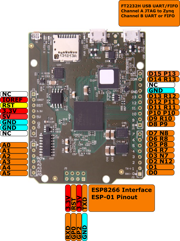 Image Removed
...
| Note |
|---|
For more information regarding how to draw a diagram, Please refer to "Diagram Drawing Guidline" . |
| Scroll Title |
|---|
| anchor | Figure_anchorname |
|---|
| title | Text |
|---|
|
| Scroll Ignore |
|---|
Create DrawIO object here: Attention if you copy from other page, objects are only linked. |
| Scroll Only |
|---|
image link to the generate DrawIO PNG file of this page. This is a workaround until scroll pdf export bug is fixed |
|
Power supply
| Page properties |
|---|
|
| Note |
|---|
The input power supply must be mentioned. |
|
Over MicroUSB (5V) possible.
DIP-Switches
| Page properties |
|---|
|
| Note |
|---|
Explain all DIP switches functionality |
|
There are no DIPs on TE0722. In case of TE0790 (XMOD) usage, see power supply section.
LEDs
| Page properties |
|---|
|
| Note |
|---|
Explain all user LEDs functionality and connection. |
|
D2(red): User LED connected to MIO9
...
D7(green): 3.3V Power LED
JTAG/UART
| Page properties |
|---|
|
| Note |
|---|
Explain JTAG or UART connection breifly. |
|
JTAG and UART is possible over miro USB connector.
...